
")
")
")
Original equipment - motors electronics
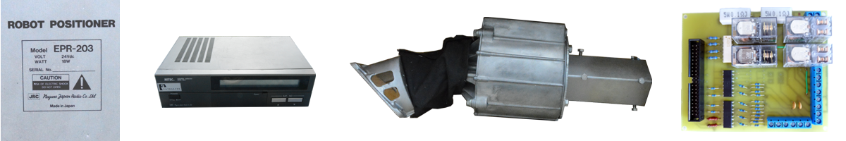
The mechanical part of the EGIS contains two motors. >Unfortunately, they are not step by step yet. They are ordinary 24V DC motors, each with a nominal consumption of 18W. They take approximately 10W without any load. However, they may take more than 20W under load, which must be taken into account.

Fig. 1 - View of the motors EPR-203
Rotation sensors are integrated in the motor body. There are two sensors in each motor. For both elevation and azimuth, external limit switches are located in the device, defining the home position. If the motors are out of home, these switches are open. Approaching the switch closes it. Therefore, they cannot be used as a safety limit switch in case the control computer bites and a motor remains energized. The switches are used only as sensors whose status is monitored by the computer. The second extreme position of both motors does not have such a switch at all. The range of motor positions can therefore only be determined on the basis of counting pulses from the motor sensors.
All signals in this section use 24V. The following figure shows the wiring diagram of the electronics of the motors and sensors in the mechanical part of EGIS.

Fig. 2 - Wiring of motors electronics EPR-203
It is clear from the diagram that several earth conductors (com) are connected to the output connector, but they are interconnected inside the device. We can connect these countries to the control unit interface with a single cable. The connector pins have the following function:
- 2, 4, 6, 8, 14 common ground of rotation sensors, ground of 24V power supply for rotation sensors
- 1 output, elevation rotation sensor, channel A
- 3 output, elevation rotation sensor, channel B
- 5 output, azimuth rotation sensor. channel B
- 7 output, azimuth rotation sensor. channel A
- 9 output, elevation zero switch
- 10 output, azimuth zero switch
- 11, 12 output, common wire of zero point switches
- 13 input, + 24V sensor power supply
- 15, 16 input, power supply 24V motor elevation. +15, -16 = move up; -15, +16 = move down
- 17, 18 input, power supply 24V azimuth motor. +17, -18 = move west; -17, +18 = move east
The output pulses of the motor rotation sensors have a frequency of approximately 400 Hz and a 1: 1 duty cycle, measured without mechanical load and thus at the highest motor rotation speed. The relative position of the pulses of the sensors of one motor can be seen in the above diagram.