
")
")
")
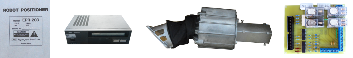
Control module for 2 servomotors for HW 1.0
Some time ago I stated that I will no longer develop or support HW version 1.0. My efforts were focused on HW 2.1 development. But the truth is that the PCB design of the new HW is still not finished, so I have to keep using my old design with relays.
At the same time, I would like to try some new things with the Laminas 2700 dish. The thing that limits me the most is the need to shoot Skew. Before I get into the mechanical construction of the LNB rotation, I have a CSP 1210 C servo driven polarizer at my disposal. I also started looking at the C-band, which I have a Corotor Chaparral ready to receive. It is also controlled by a servo motor. That's why I decided to make the servo motor control part from HW 2.1 as a separate module for HW 1.0.
I must stress that my decision not to continue developing HW 1.0 remains unchanged. This article is only informative for inspiration. I don't expect the SW of this module to be published in the future, which is necessary for its operation.
The module diagram is taken from HW version 2.1. No adjustments needed to be made to this section.
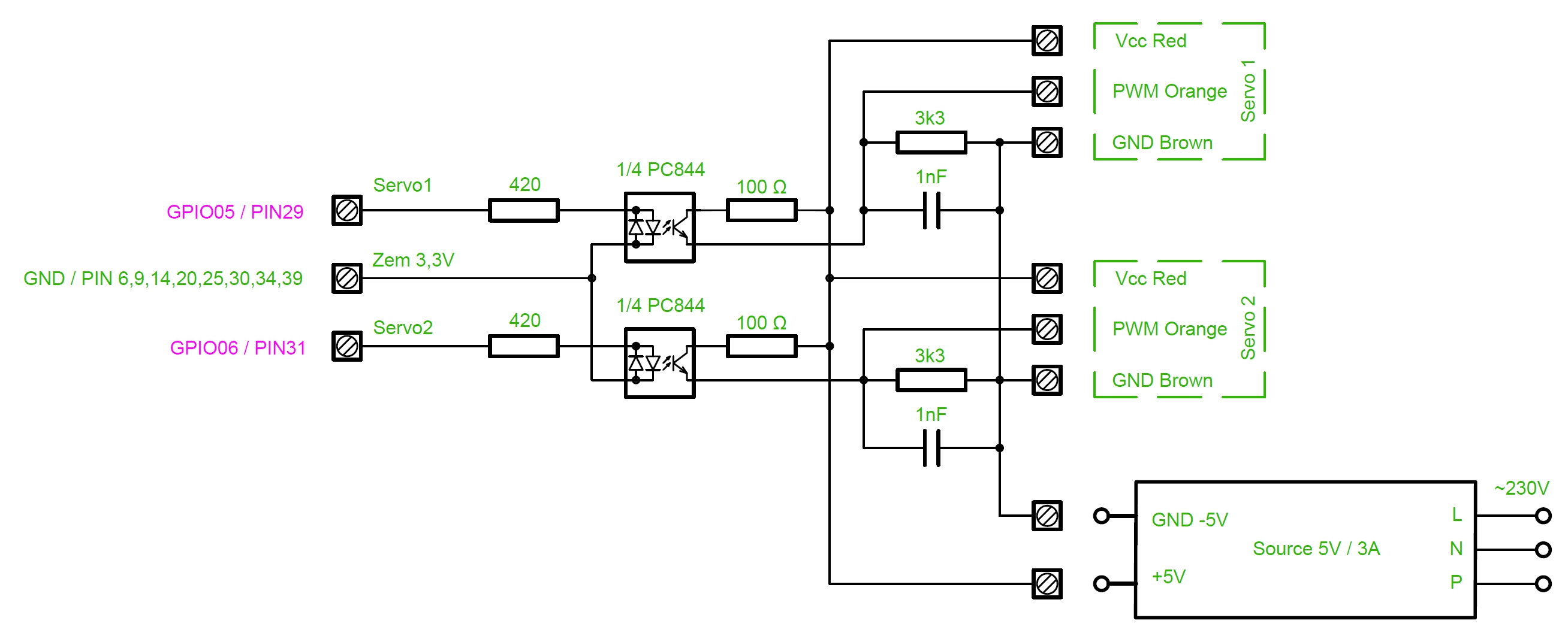
Fig. 1 - Diagram of the servo motor module
The signal for controlling the servo motors is created using software-generated PWM pulses. This signal is galvanically separated by optocoupler PC844, converted to 5V level and fed to the control input of the servomotor. The polarity of the signal is important, which is ensured by the 3k3 and 100R resistors. I have a cable about 17m long between the module and the servomotors. A 1nF capacitor filters out interfering RF signals induced into these wires.
The following table lists the parts used:
| Part number | Component name | Quantity |
|---|---|---|
| 8 | Source 5V / 1 ÷ 3 A | 1 |
| 7 | Terminal block ARK500/3EX (Wago W237-103) | 3 |
| 6 | Terminal block ARK500/2EX (Wago W237-102) | 1 |
| 5 | Condenser 1nF, ceramic, foil | 2 |
| 4 | Resistor 3k3 | 2 |
| 3 | Resistor 420Ω | 2 |
| 2 | Resistor 100Ω | 2 |
| 1 | PC844, 4x optocoupler (Vishay ILQ620) | 1 |
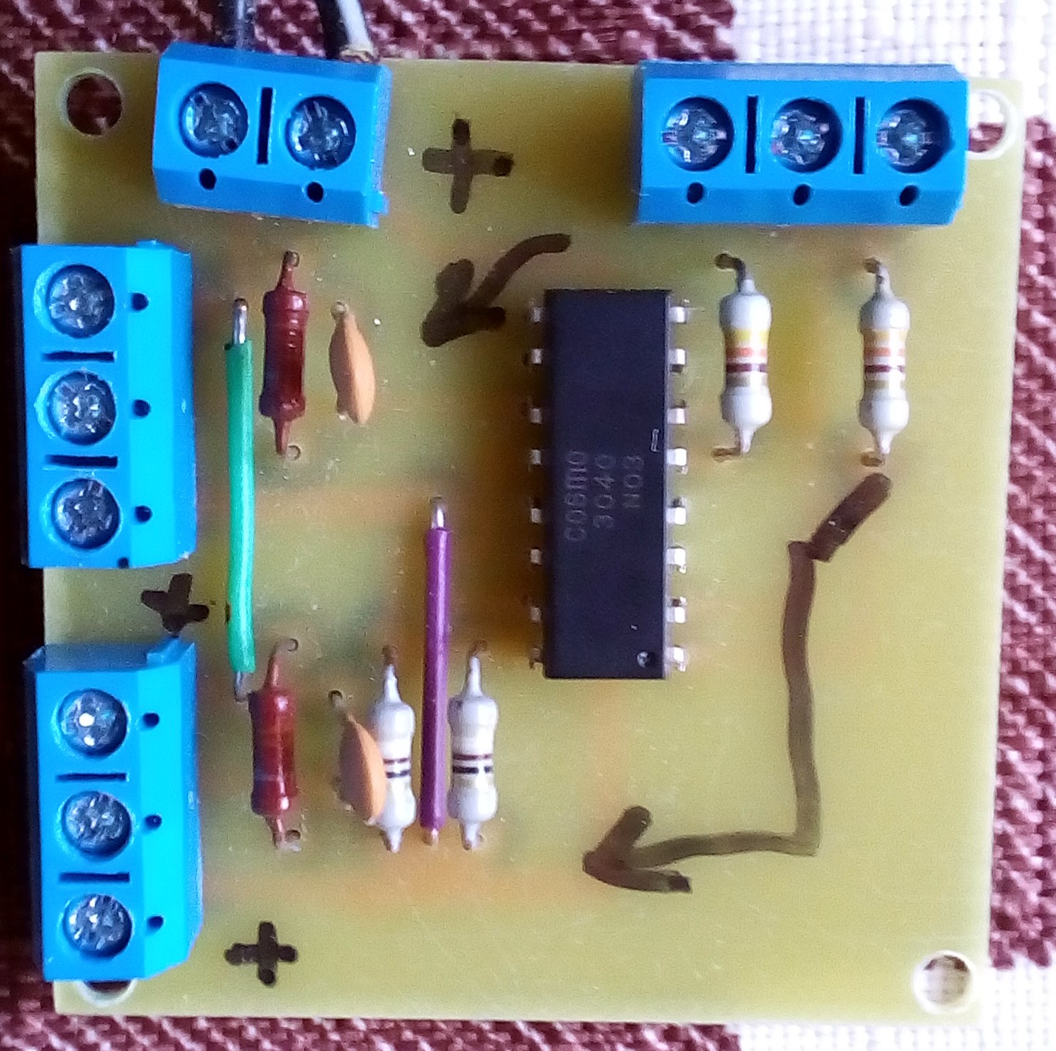
The module is quite simple, so even designing the printed circuit board was not a lot of work. Almost all joints were squeezed into one layer. In the end, only two wire jumpers needed to be added.
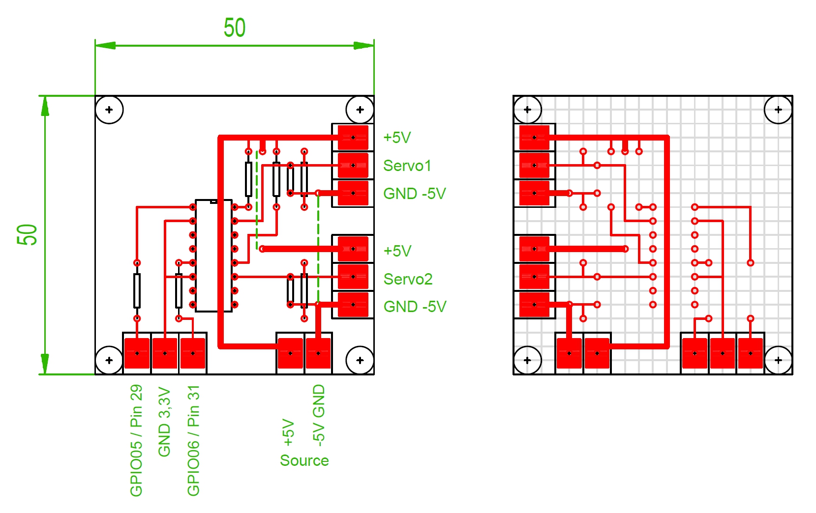
Since I have the control unit located in the attic of the house in a dry environment, I did not consider it necessary to place the module in a box. The module is connected to the positioner using three wires. One is brought to the ground of the Raspberry Pi and must not be connected to the ground of any other part of the structure. The other two wires are connected to the GPIO connector. Selecting specific ports was easy. In HW 2.1, GPIO05 (pin 29) and GPIO06 (pin31) are used to control the servo motor. Since in HW 1.0 these pins are not used yet, there is no reason to change them.
The 5V source deserves a separate note. Since there is already such a resource in the construction, it would be tempting to use it. But in the end I decided to use a separate resource. Because servomotors can consume quite a lot and one source could already react to changes in load by changing the output voltage. And this could affect the operation of the Raspberry Pi computer. Moreover, it is only a temporary solution, so I wanted to limit the module's dependence on the original design to a minimum.
I want to gradually switch from javascript to python for the control program. I thought this was a great opportunity to try my hand at it. Python is a somewhat specific programming language and you need to get used to it.
Since I did not dare to write my own web server right from the start, I used a ready-made solution in the form of the Flask framework. It is recommended to install it via pip. But it is not absolutely necessary. Next, you need to select the libraries that will be used to access the GPIO ports. In the end I chose PiGPIO. It has the peculiarity of running its own daemon, i.e. a background service through which it communicates. What this means in practice is that communication with the Raspberry Pi ports is a separate program, the speed of which is not directly related to the user program in python.
Well, the rest of the proposal was already up to me. I gradually worked my way up to a program that allows direct control of two aegis motors and one servo motor. It also includes presets that automatically set the saved positions of all three motors. The current position of all motors can be stored in these presets with the Store mem button, or they can be deleted with the Clear mem button.
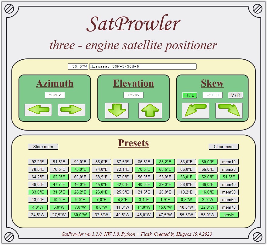
Controlling a single servo is sufficient for my purposes at this point. The servomotor is intended for setting the Skew, i.e. "only" for the mechanical rotation of the LNB according to the selected satellite. However, the CSP 1210 C and Corotor Chaparral polarizer have a rectangular waveguide at their output for connecting a single-polarity LNB. They also use a servo motor to change the horizontal and vertical polarization. Therefore, in addition to shooting Skew, I had to add the H/L and V/R buttons to the program, which jump-turn the receiving antenna in the input waveguide by 90°. The actual Skew is then set as the middle position between these two positions.
The program indicates how the control of HW version 2.1 will probably look like. When I get its prototype up and running, I'll write a detailed process of working with said SW in a separate article. It looks like 60 presets will probably not be enough. But only practice will show these details. I'm quite curious how many presets you use in the positioner. (Do you really have to have all the satellites visible from your location set in the positioner?)