
")
")
")
HW 1.0 Practical design
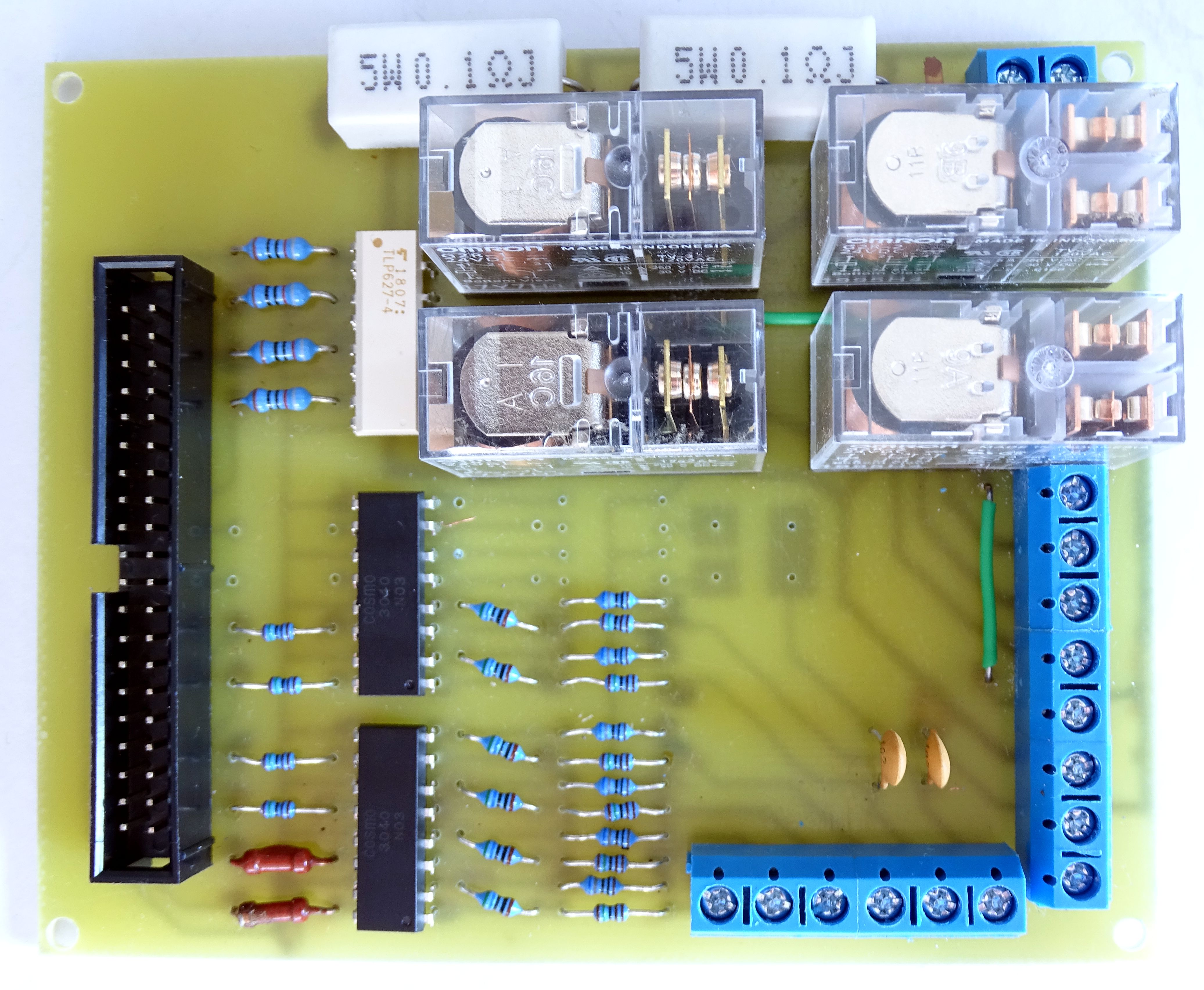
I designed a printed circuit board for the mentioned HW. I tried to invent it so that even a more skilled amateur at home could make it. That's why I only chose a single-sided PCB. The placement of the components is not optimal and two wire jumpers are required.
Data links that do not carry any larger streams are drawn in red and their width does not matter much. The power supply of the motors is drawn in blue and should be as strong as possible, estimated at around 1mm.
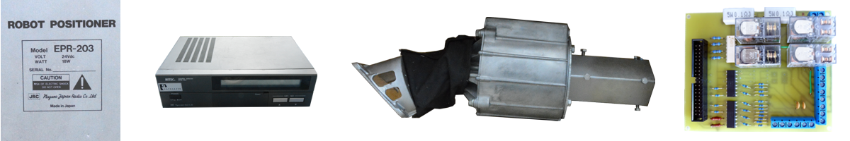
The first picture is a view of the printed circuit board from the side of the components. The second picture shows a separate printed circuit board. It is a bottom view, so it is mirror-inverted. The third figure shows the layout of the components with their designation.
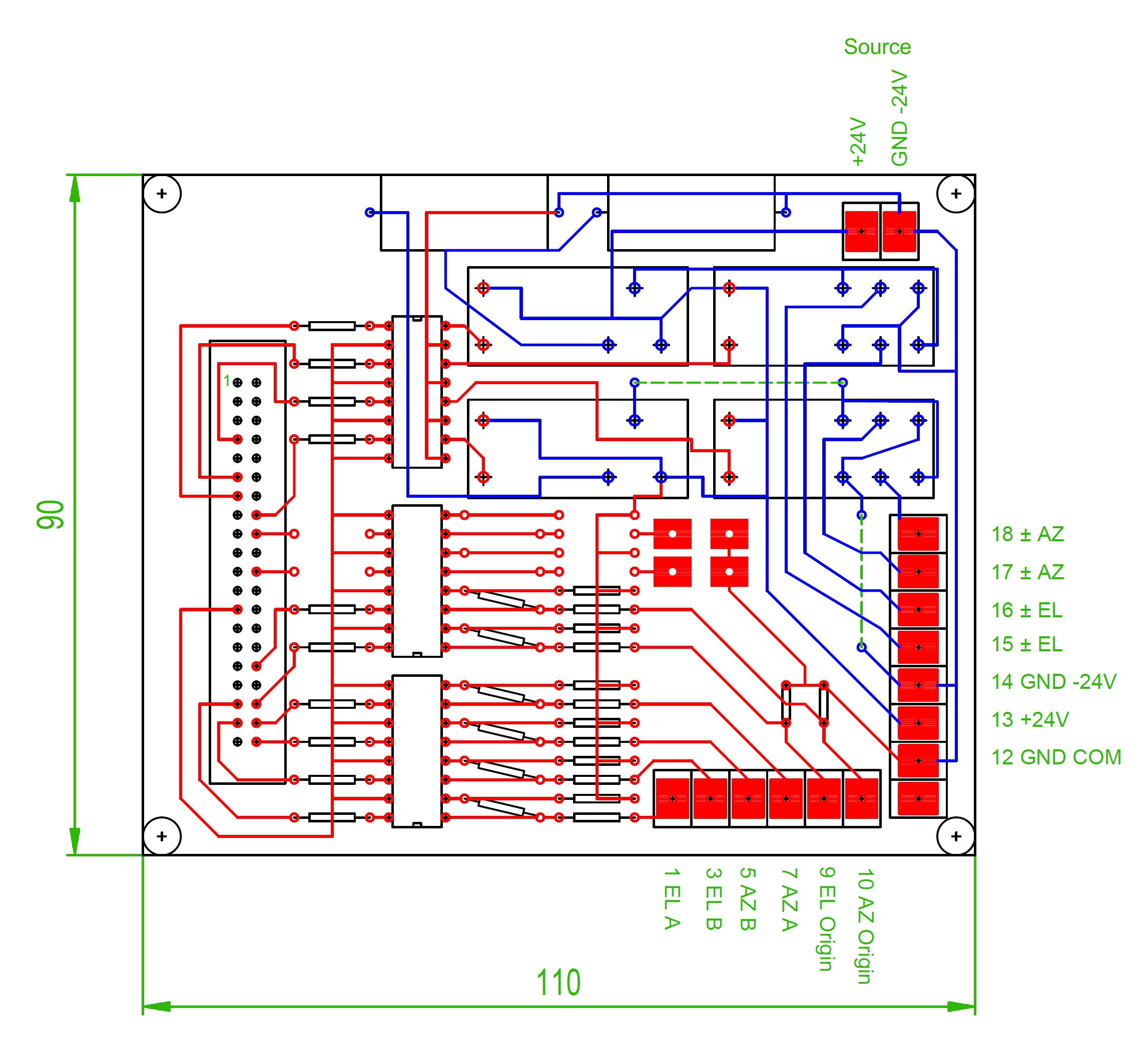
Fig. 1 - PCB on the part of components
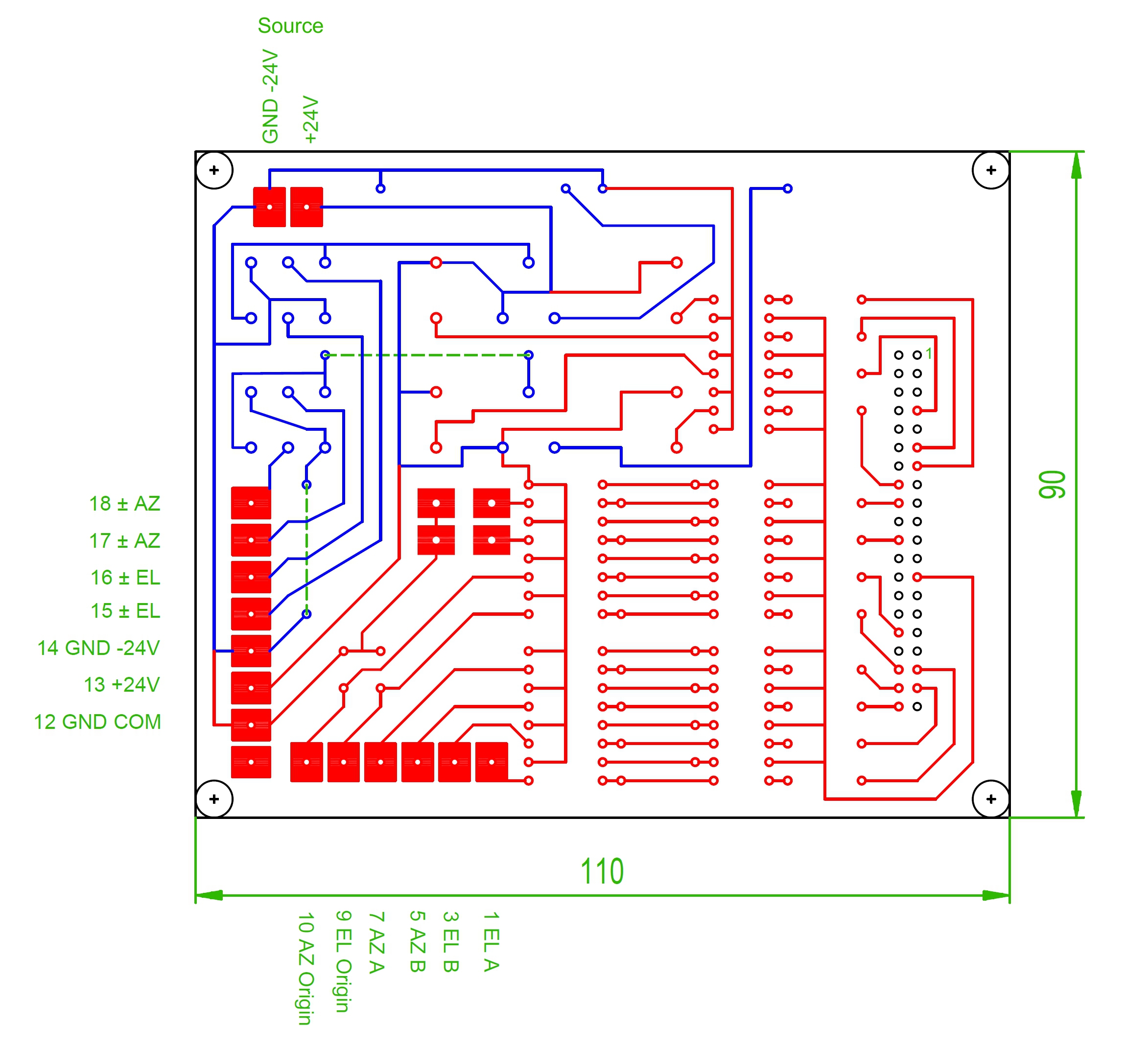
Fig. 2 - PCB on the connection side
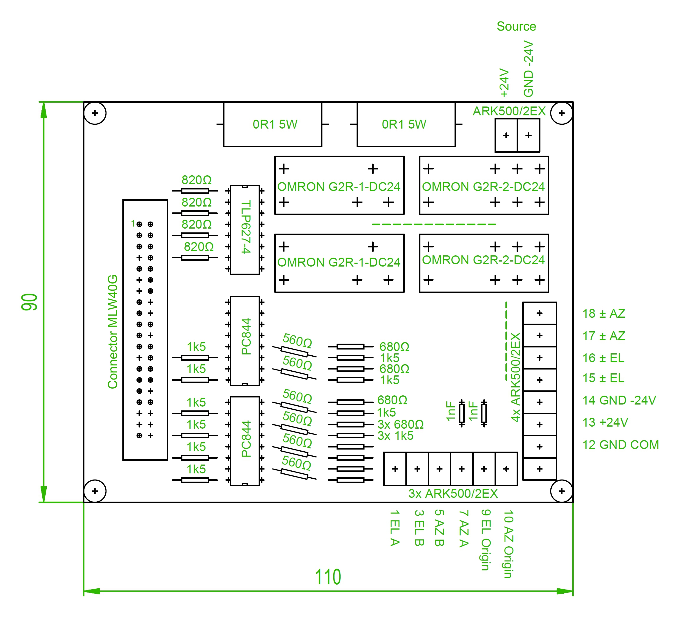
Fig. 3 - Component placement on a PCB
And here is the finished prototype. I made the printed circuit board myself at home, so to speak, "on my knees", so I checked that it can really be produced in this way by myself.
In one PC844 integrated circuit, two optocouplers remain unused. I did not install the components around them, but the printed circuit board is ready. After adding resistors, two more switching inputs can be used on ports GPIO24 (PIN18) and GPIO25 (PIN22). Any mechanical model can be used as a switch. In that case, it would be appropriate to add filter capacitors such as those on the Origin inputs. When using an electronic switching element, it is necessary to keep in mind that the adjoining resistance network is connected to a voltage of + 24V and is connected to the ground of the 24V source. The 24V supply ground and the Raspberry Pi ground must never be connected.
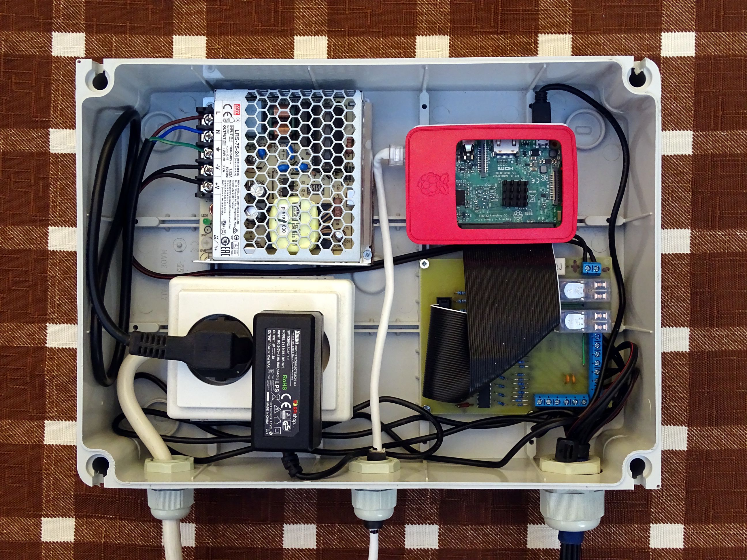
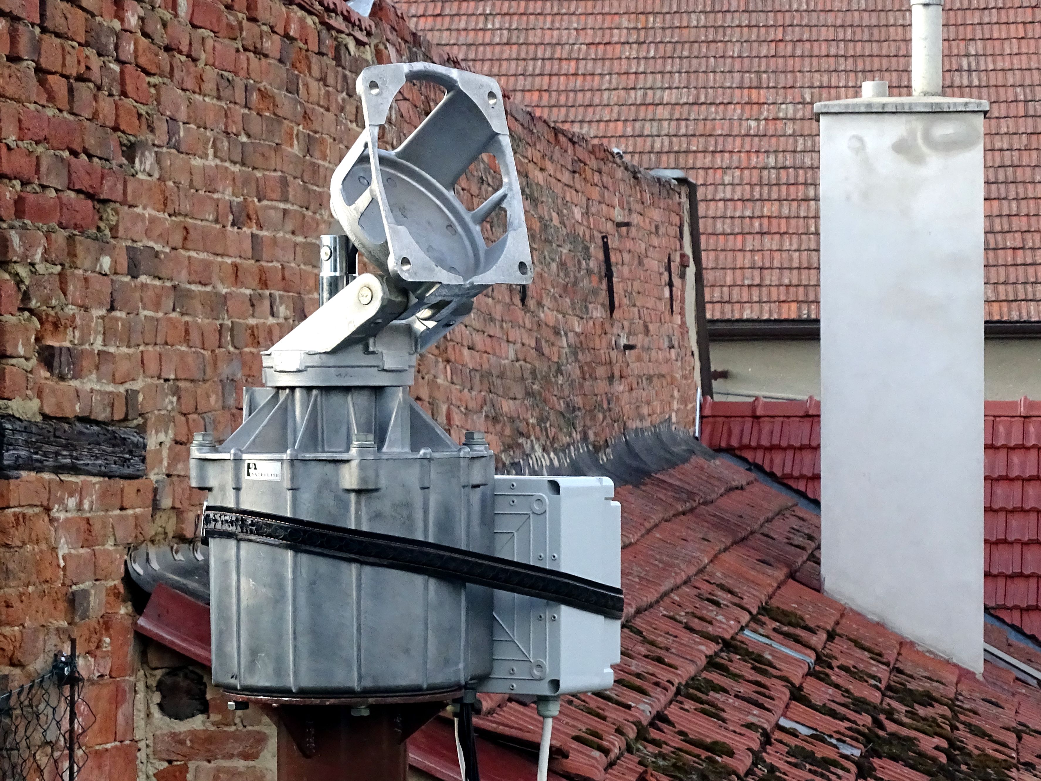
The entire device will be located outdoors near the EGIS positioner on a support mast. That's why I bought a plastic waterproof installation box with dimensions of 300x220x120mm with IP65 protection. That should be enough to protect against rain. I placed a double 240V socket in the box, which supplies the Raspberry Pi and a 24V switching power supply. In the bottom wall of the box there are three cable glands - a 240V power cable, an Ethernet cable and cables connecting to the positioner.
21.10.2020 Appendix.
Maybe I misunderstood the technical term "waterproof". I thought water couldn't get into the waterproof space. Error. The point is that once water appears in the watertight space, it is no longer able to get out. :-)
After two months of using the EGIS positioner with my control, something went wrong. The device has stopped working. After opening the waterproof box, I found that there was half a liter of water inside. The Raspberry Pi was definitely drowned and I had to throw it away. The switching power supply runs after drying, but my HW controlling the motors is dead. I dried the whole interior space, closed the box again and covered everything with plastic. Although it didn't rain for the next two days, there were drops of water inside the box after reopening. There appear to be gaps around the ribbon cables leading to the EGIS positioner, where moist air enters. And that's enough to make water droplets slowly condense from it over time.
This would mean that the box needs to be sealed really hermetically so that not even air can penetrate inside. At a minimum, it would be necessary to seal the cable glands with some glue. Despite this measure, I have no idea if moist air can get in through the rubber seal of the waterproof box. A more reliable solution would be to drill ventilation holes in the lower part of the box, where possible water could flow out. And provide the entire structure with additional protection against direct rain. But since I have a mains voltage of 240V inside, I don't like this situation at all.
Therefore, I prefer to take advantage of the fact that less than 10 m from the positioner I have accessible attic of the house. When I repair the control unit, I leave it placed dry under the roof. This will check whether the entire system is functional even when connected via 10 m long cables. At the same time, I will have a sheltered workplace, where I will continue to develop the control unit. I'm already starting to prepare HW construction number 2.
29.11.2020 Appendix.
I managed to fix my "drowned" control. The corrosion interrupted a few paths on the printed circuit board, so it was enough to replace them with wire jumpers. I did not want to return the corrected control to the outdoor environment. Mainly because I am developing a prototype of the new version HW 2.0, so I need to be able to work on the unit even in adverse weather conditions. That's why I placed the control unit on the ground and connected it to the EPR-203 motor unit with 10 m long cables.
I am aware that data cables from sensors and zero switches should be shielded. But I wondered how these control unit inputs would be interference resistant. The value of "logical 1" = 24V is quite a lot. So I assumed that the immunity to interference should be sufficient, even if the cables are 10 m long and tied close together. And that was also confirmed. Even a repaired unit connected in this way works perfectly correctly.
But I'm not sure if the same cabling can be used for HW 2.0. Here the motors will be powered by pulses with an amplitude of 24V and this will already create quite strong interference. False pulses could appear at the inputs to the control unit. The fact that the pulses from the sensors have a frequency of 400 Hz also adds to this danger. When I discussed with Jeff the appropriate frequency for PWM motor control, I learned that he uses 500 Hz. Which is pretty close to frequency. I don't want to draw any hasty conclusions from this yet, but in this case it will probably be necessary to shield the data cables.
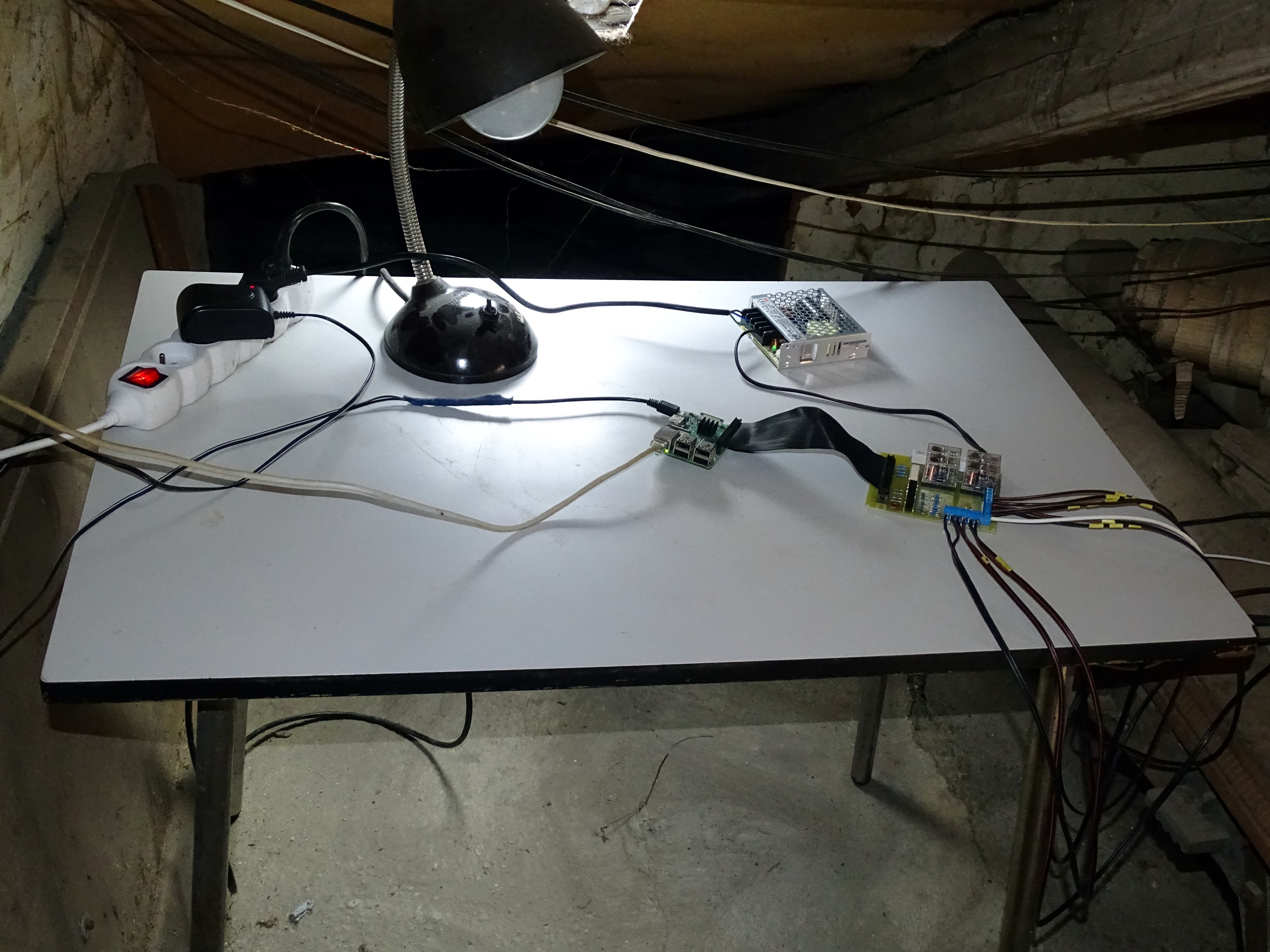
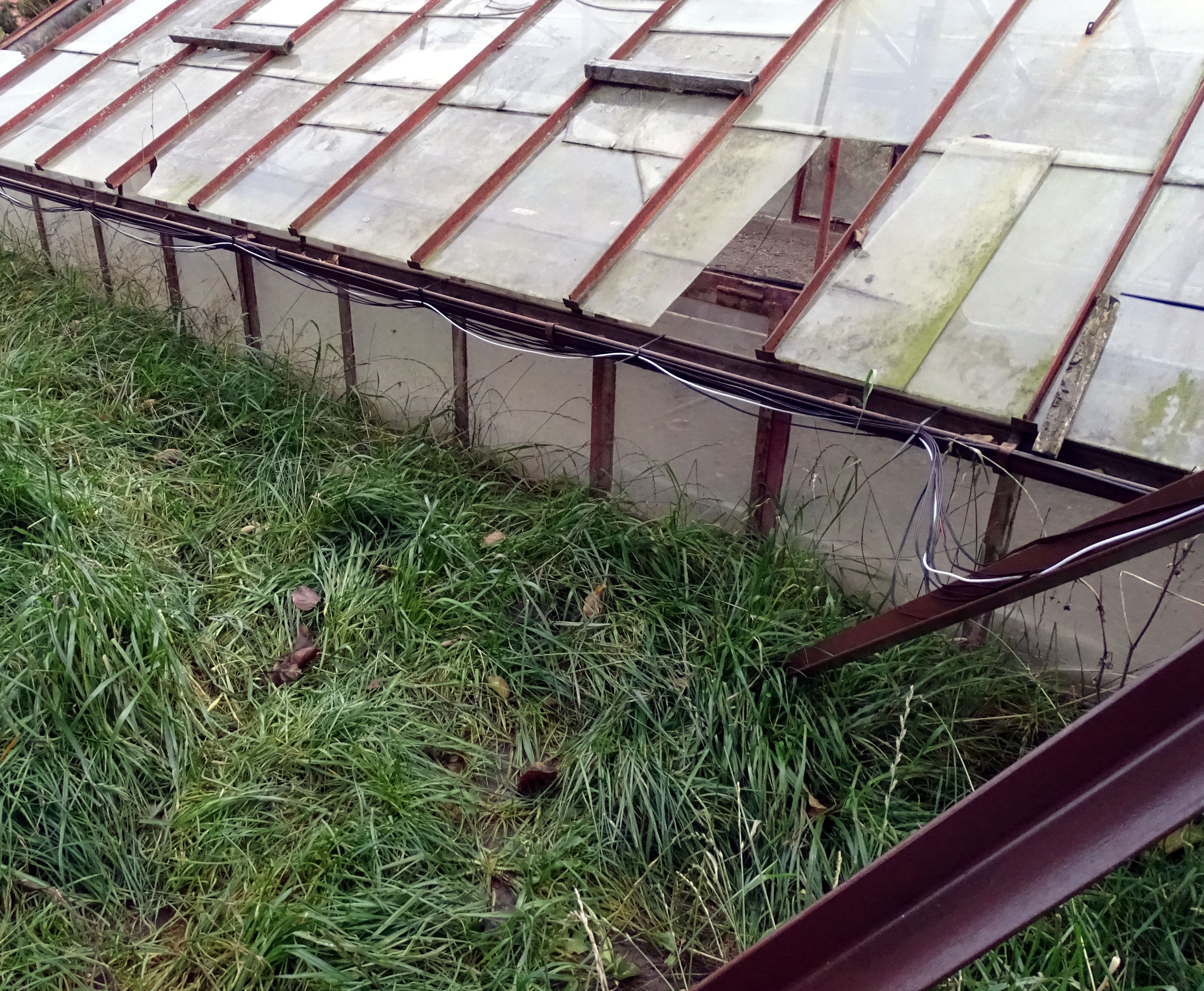
Fig. 8 - Temporary development workplace
So I set up a temporary development workplace for the repaired control unit in the attic of a nearby house. Thanks to this, I don't have to return the individual components to the cramped space of the original box and the cables are freely accessible for connecting the prototype of the new HW 2.0. The weather won't keep me from work, but I still have to hurry before the big frosts come. So maybe soon ...