
")
")
")
Introduction - how it all started
In 2019, I became the lucky owner of the Egis shooting facility. I bought the device for an advertisement from Italy. At first glance, I seemed quite lucky, because everything seemed to be in very good technical condition. According to the label on the mechanical part, the official name of the device is ROBOT POSITIONER EPR-203 and the manufacturer is the Japanese company Nagano Japan Radio Co., Ltd. Which was a bit of a surprise for me, because today the official manufacturer is the German company EGIS GmbH. But that did not end all surprises.
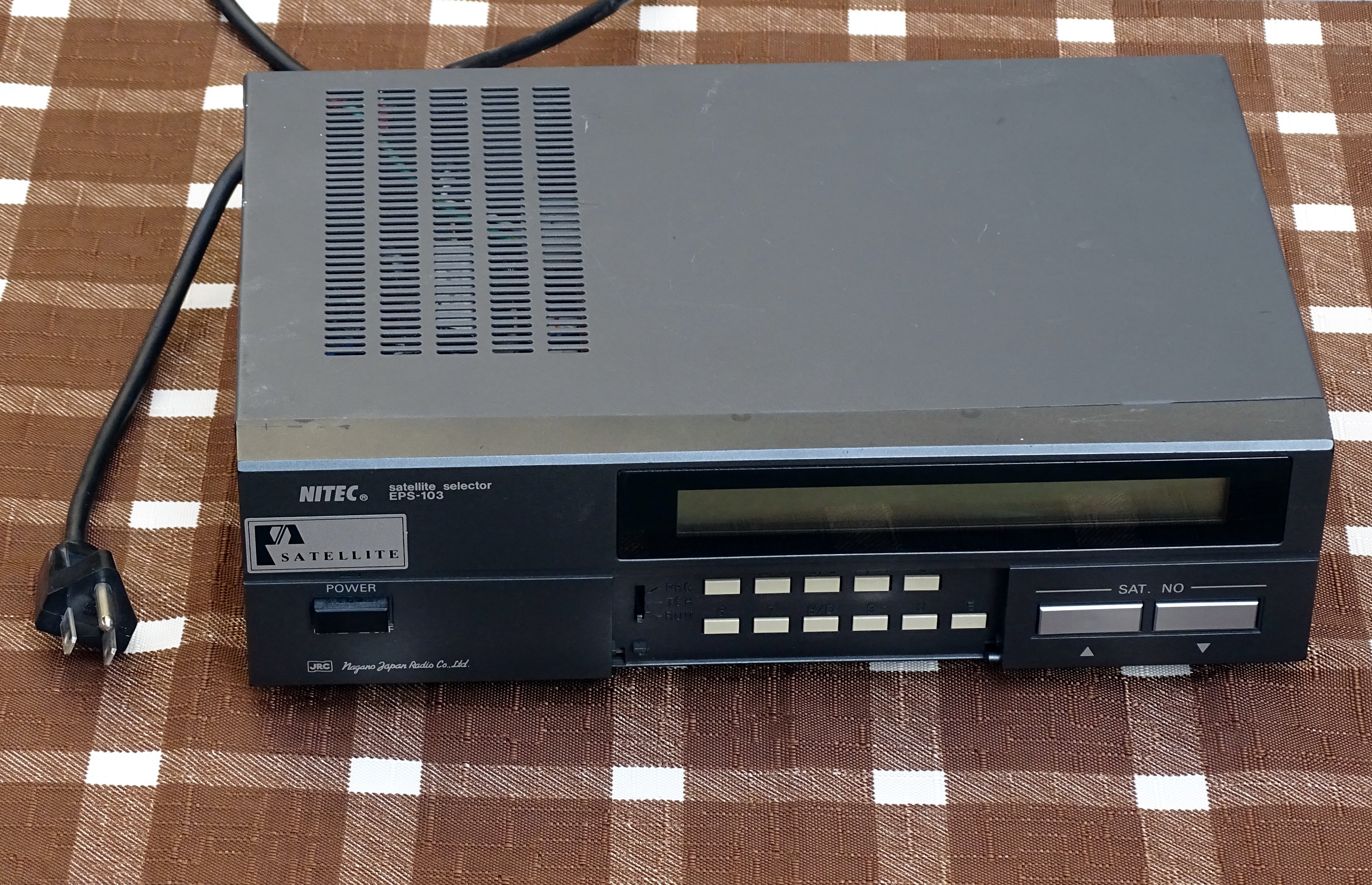
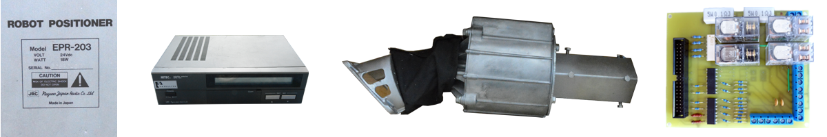
Fig. 1 - Original NITEC EPS-103 control unit
The mechanical part is controlled by electronics marked NITEC Satellite Selector EPS-103. This electronics requires a mains voltage of 100V (120V) from the mains. Fortunately, the set also includes a CV 100 conversion transformer, which converts the usual 240V to 100V in our country. But there was a plug on its network cable that didn't look like anything usable in our region. So the whole rotator could not be tested.
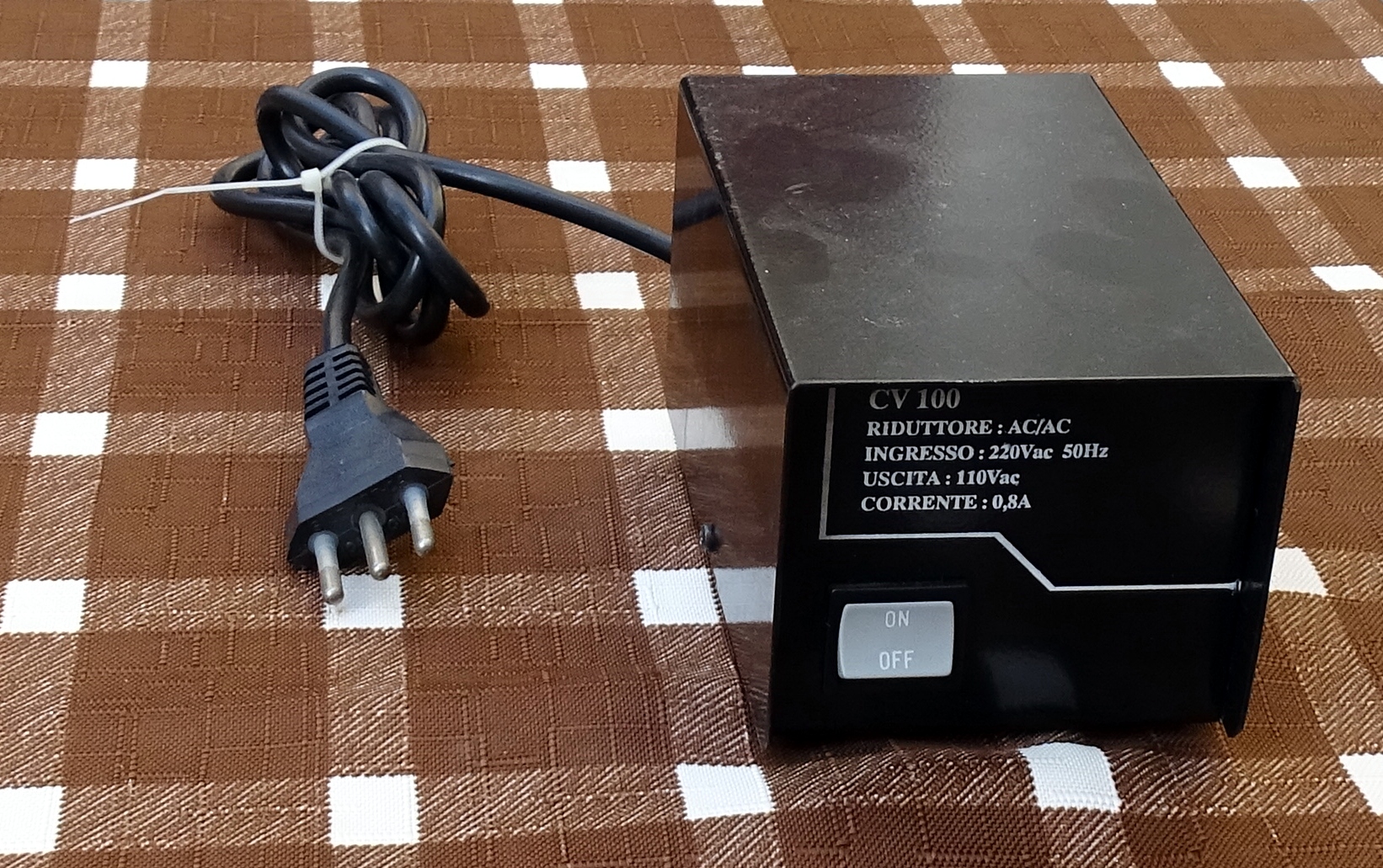
Fig. 2 - Conversion transformer 240V / 100V
I started looking a bit and I found out that in Japan they still have only 100V in the sockets. Logically, the electronics are adapted to this voltage. The conversion transformer from 240V to 100V was probably subsequently bought by the Italian owner. But in Italy they have the same voltage in the sockets as we do, but unfortunately they use different terminals. So I slowly began to come to terms with the idea that I would have to make adjustments. I had no idea how extensive these adjustments would be.
The first step in putting the rotator into operation was to replace the original Italian network cable with a Czech one. After opening the CV 100 transformer, I was happy. The Italian cable has the same color marking of individual wires as our Czech one. So I couldn't confuse their involvement. All you had to do was re-solder them.

Fig. 3 - The inside of the transfer transformer CV 100
The next step was to connect the control box with the electronics of the motors in the mechanical part. It turned out that it will take a while, because there are really a lot of wires. At this point, I did not yet know the design of the device, but I did not want to investigate which jumpers are power for motors and which data for control and could possibly require shielding. I told myself that for a test distance of 2m I would use all unshielded wires with a larger cross section. A total of 14 wires are needed.
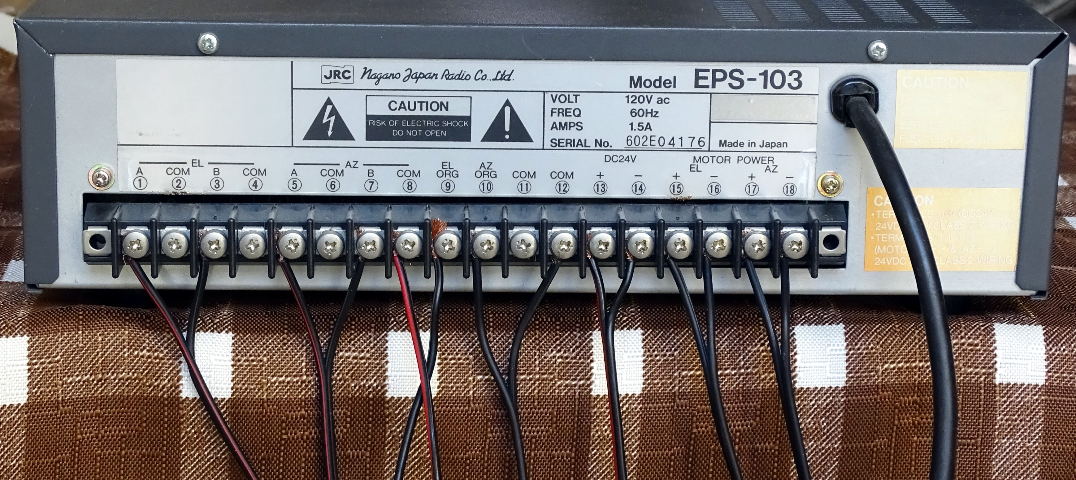
Fig. 4 - Control unit bus NITEC EPS-103
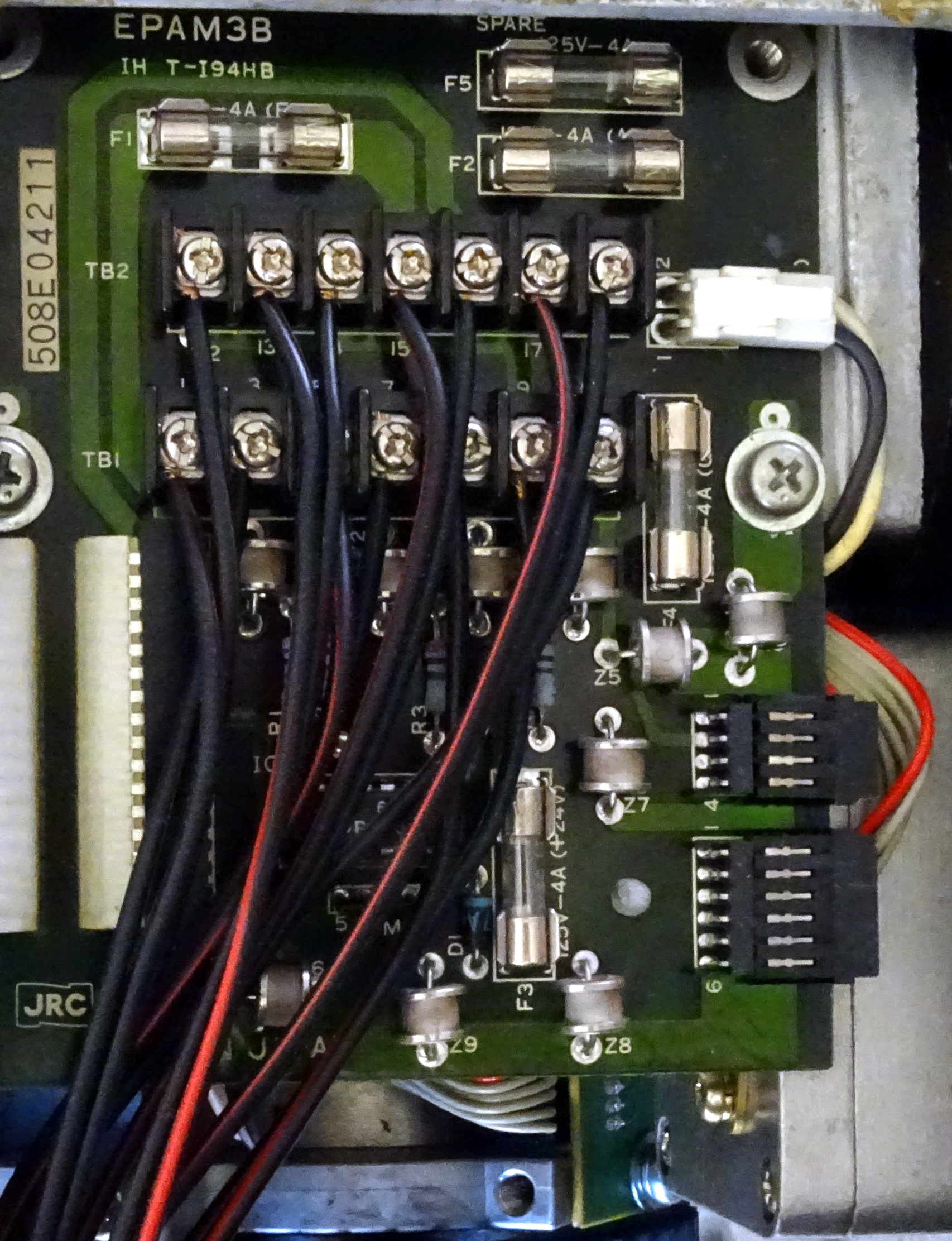
Fig. 5 - Motors electronics bus EPR-203
After switching on the device, it waits for the selection of a satellite. According to the manual, there are 16 pre-programmed positions in the device and another 16 positions can be programmed by the user. It is selected using the + and - buttons. After selecting the satellite, the motors are first set to zero positions. The elevation motor moves to the limit switch first. The motor, which rotates horizontally, does the same. After reaching the starting points, the device is set to the selected position. During further use, the positioner rotates directly to the position according to the newly selected preset. Again first elevation and then azimuth.
After the first enthusiasm that everything works as it should, I started to study the design more. And gradually I found out that my adjustments probably won't stop just when replacing the mains plug. A very surprising feature was that both shooting engines do not work at the same time. After selecting a new position, the rotator always first set the elevation and only then began to rotate around the vertical axis. That seemed strange to me. After all, this significantly increases the time needed to adjust to a new position. I opened the control box and a major surprise awaited me here. The digital part is built on an 8-bit 8085A processor.
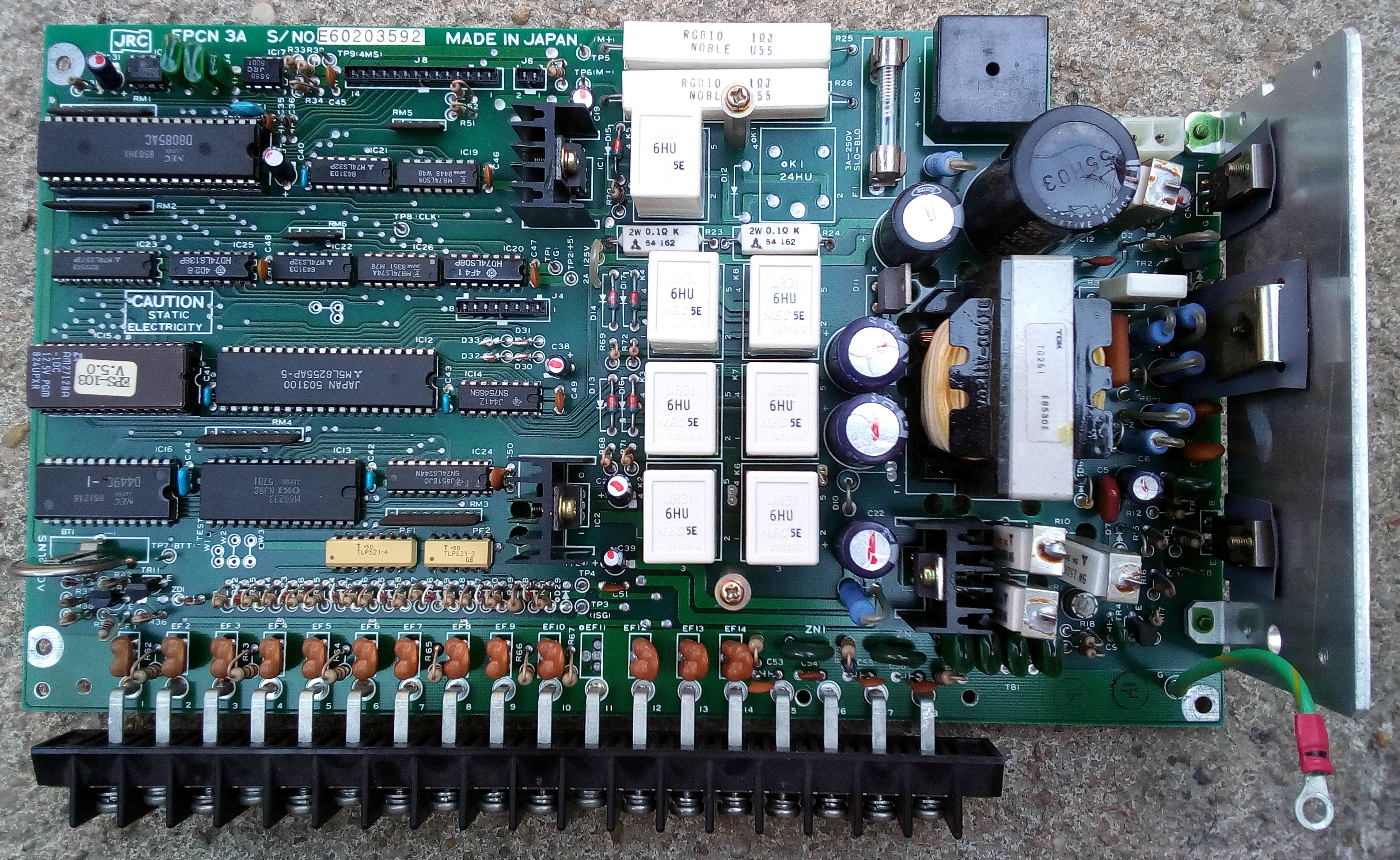
Fig. 6 - Electronics of the original control NITEC EPS-103
The whole facility is technologically perhaps 35 years old. This may be the reason why the engines start gradually. Perhaps to reduce the required controlled power. Or the computer cannot monitor the input data from all sensors at once. I don't know. But at this point, I have clearly started thinking about replacing the control unit with my design from the current components.
But the truth is, I don't really know if I set the bar too high. If someone wants to join and participate in the development, especially the software part, I will definitely not refuse help. In that case, please contact me via e-mail address