
")
")
")
Supporting structure for EGIS positioner
I started to invent the supporting structure for the placement of the positioner with the idea of placing a Polish dish Laminas AS-2700 on it. Since I have never had such a large dish and I have no idea what forces will act on such a plate in the wind, I decided to place it in a temporary place for now. Here I will check the durability of the mechanical construction and at the same time the dish will be easily accessible from the ground. This is suitable for experiments with different LNBs and different transmission bands. Only after practical experience will they begin to consider the final placement. Therefore, the stated dimensions of the supporting structure are only emotional and experimental. Whether they are insufficient for the said dish or, on the contrary, oversized will be shown by practice.
I chose a place for the mast next to the old greenhouse. Its concrete foundation will be used for two anchor points. From the L40 profile, I made something like an inverted horseshoe with dimensions of 500 x 250 mm. I drilled 5 holes for dowels with a diameter of 12 mm into the concrete and screwed the horseshoe. I really have no idea here how solid the handle was created in this way.
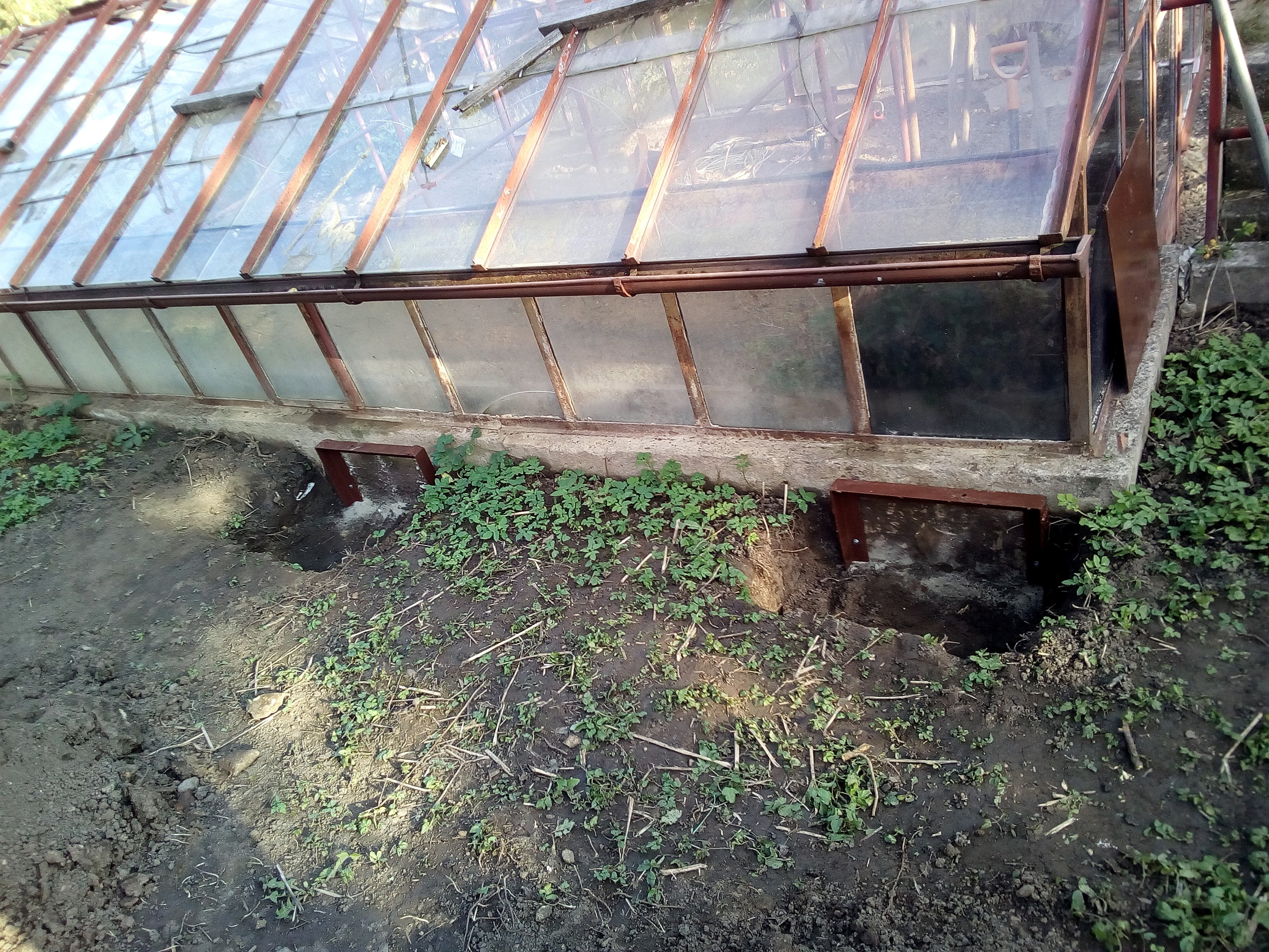
Fig. 1 - Fixing points in the concrete base of the greenhouse

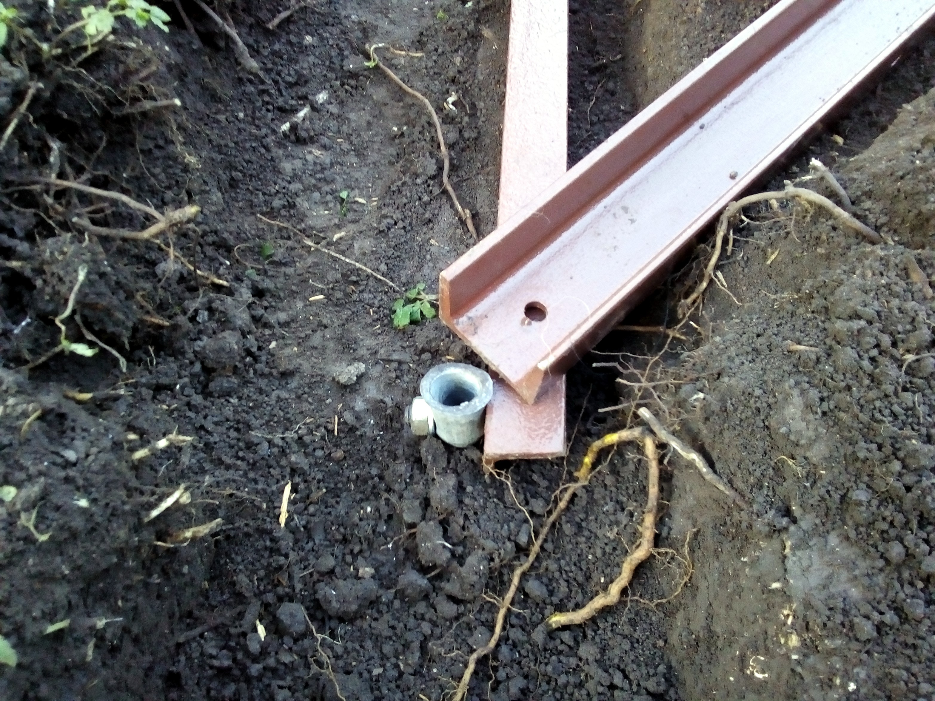
Fig. 2 - Detail of the attachment point in the concrete base of the greenhouse
As two other anchor points, I used 1.5 m long pipes with an outer diameter of 28 mm driven into the ground. Because the habitat is only temporary, I didn't want to pour more concrete into the flowerbed in the garden. Originally I wanted to use pipes with a length of 2m, but I did not manage to drive them so deep myself. These pipes are connected on the surface with a U50x40mm profile. Two more anchor points of the base are then placed on this profile. As an additional safeguard, I plan to place an old cherry trunk on this side, which weighs an estimated 150 kg.
I used four U65x48mm profiles for the base for the support tube. The length of one beam is 1.4 m. The base therefore has dimensions of approximately 2.1 x 2.1 m. This sheet should prevent the structure from sinking into the clay during the rainy season and also serves to connect the center ends of all four profiles.
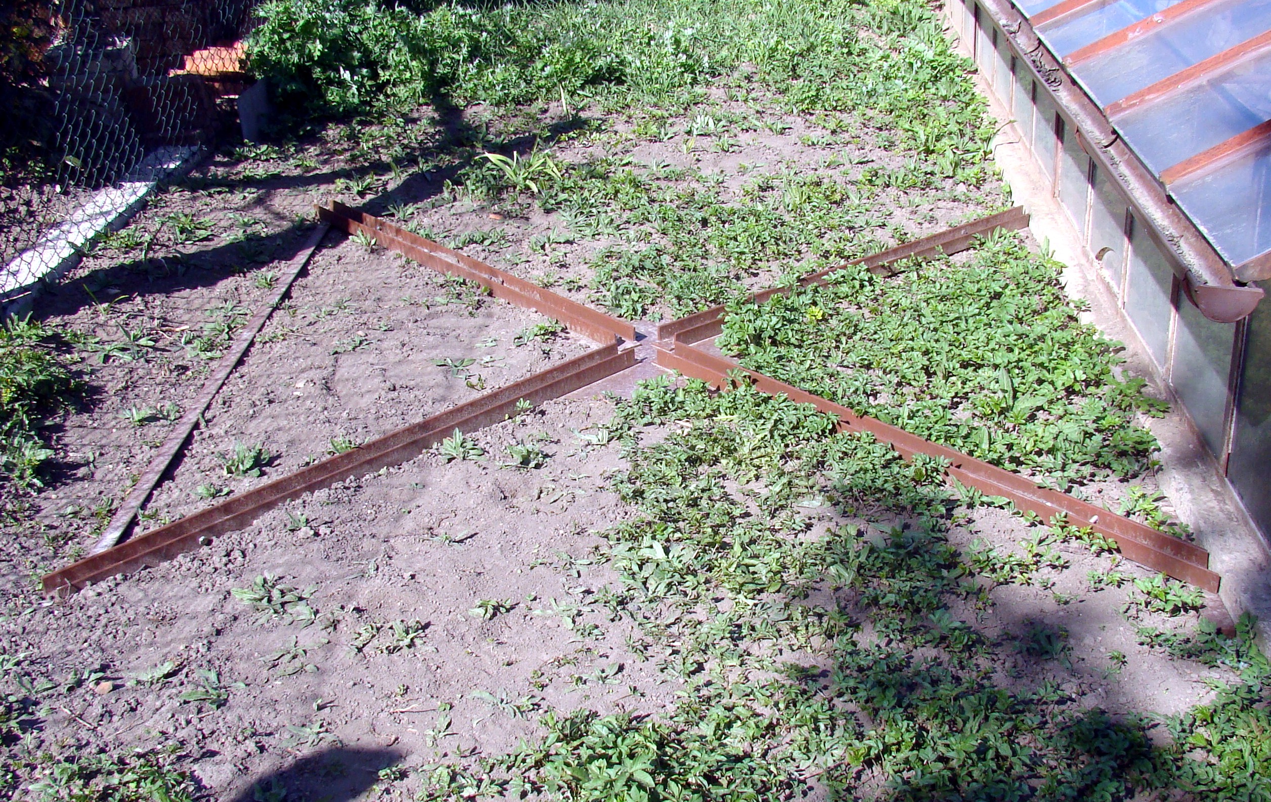
Fig. 5 - The base of the supporting structure

Fig. 6 - Detail of the center of the base
I made notches at the ends of the profiles, so that the support tube stands not only on the base plate, but at the ends of all four spokes of the base. This will spread the weight over a larger area. The space between the notches is slightly larger than what is needed for the support tube. By moving the base of the support tube, the verticality of the structure can be slightly adjusted. However, this setting is not important for twin-motor control of the dish.
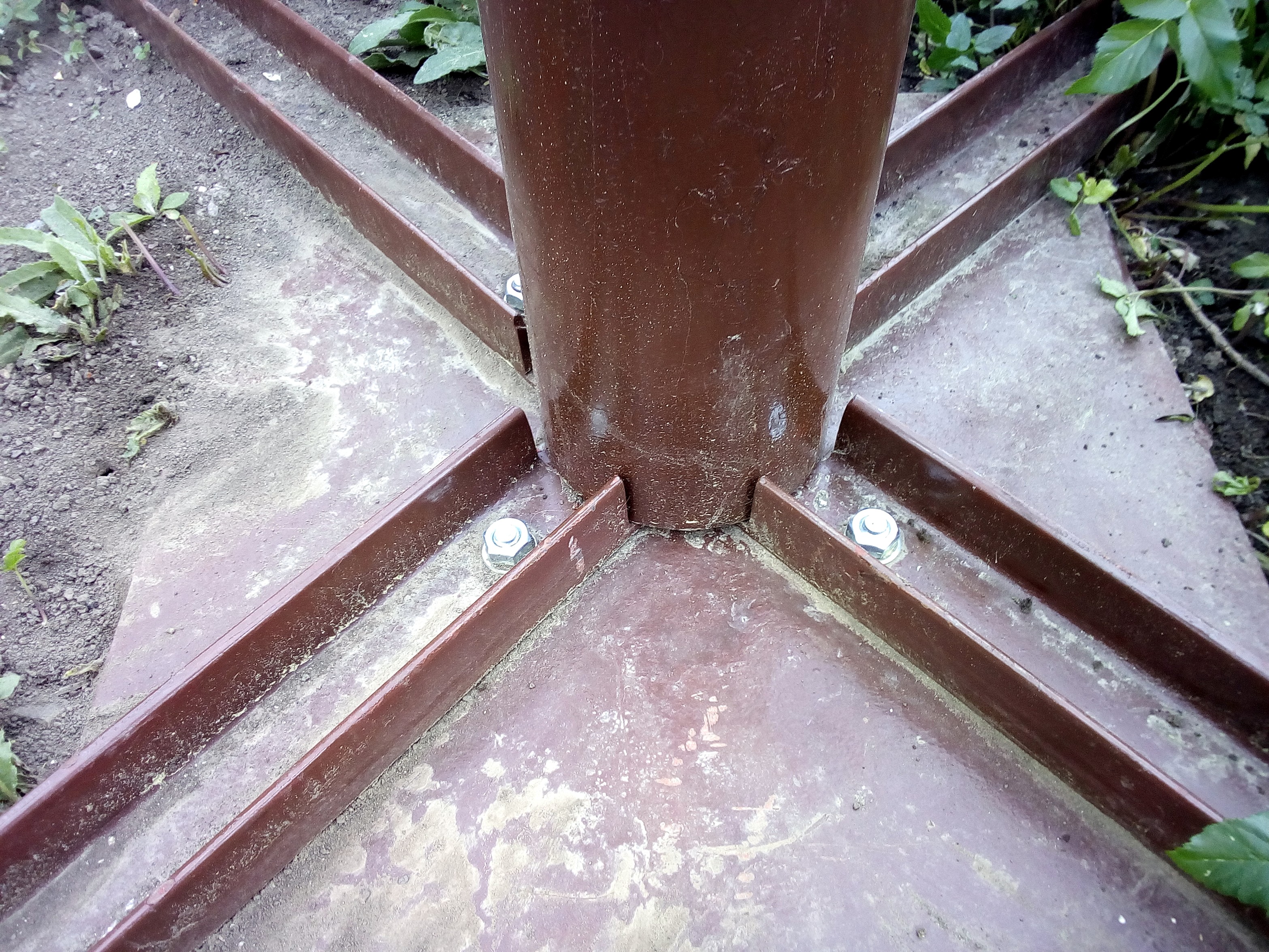
Fig. 7 - Location of the base of the support tube
I chose a support tube with a diameter of 130 mm and a wall thickness of 3 mm. Because the EGIS should point correctly to the north, I needed to be able to rotate with the support tube. That's why I didn't weld the handles for the supports to it, but I created a ring made of 25 x 5 mm web, which, after the correct rotation of the support tube with the rotator, tightens and thus secures it against further movement.

Fig. 8 - Annular sleeve of the support tube

Fig. 9 - Annular sleeve of the support tube
I originally also wanted to make supports from the U profile, but at the time of purchase they did not have any suitable ones. That's why I used the L50 profile. It is ugly, but functional and later it can be gradually replaced by the originally intended U-profile. The length and location of the supports is a bit problematic, because the antenna under consideration has an offset of 25.5 °. Its lower edge could catch on these supports if directed close to the horizon. That's why I chose a compromise between gripping force, dimensions and location. Finally, the length of the supports is 1.6 m and with the supporting tube and base it forms a triangle with sides of 1 m and 1.2 m.

At the upper end of the support tube, a circular part with a diameter of 248 mm and a thickness of 6 mm is welded. This is the original part of the positioner unscrewed from the bottom. EGIS is attached to this part with four M12x35 screws. It must have a hole with a diameter of 80 mm in the middle for the movement of the screw adjusting the elevation. This part is supported by four small ribs 55 x 55 mm for safety. The holes for screwing the rotator are located in the vertices of a square with an edge length of 150 mm.
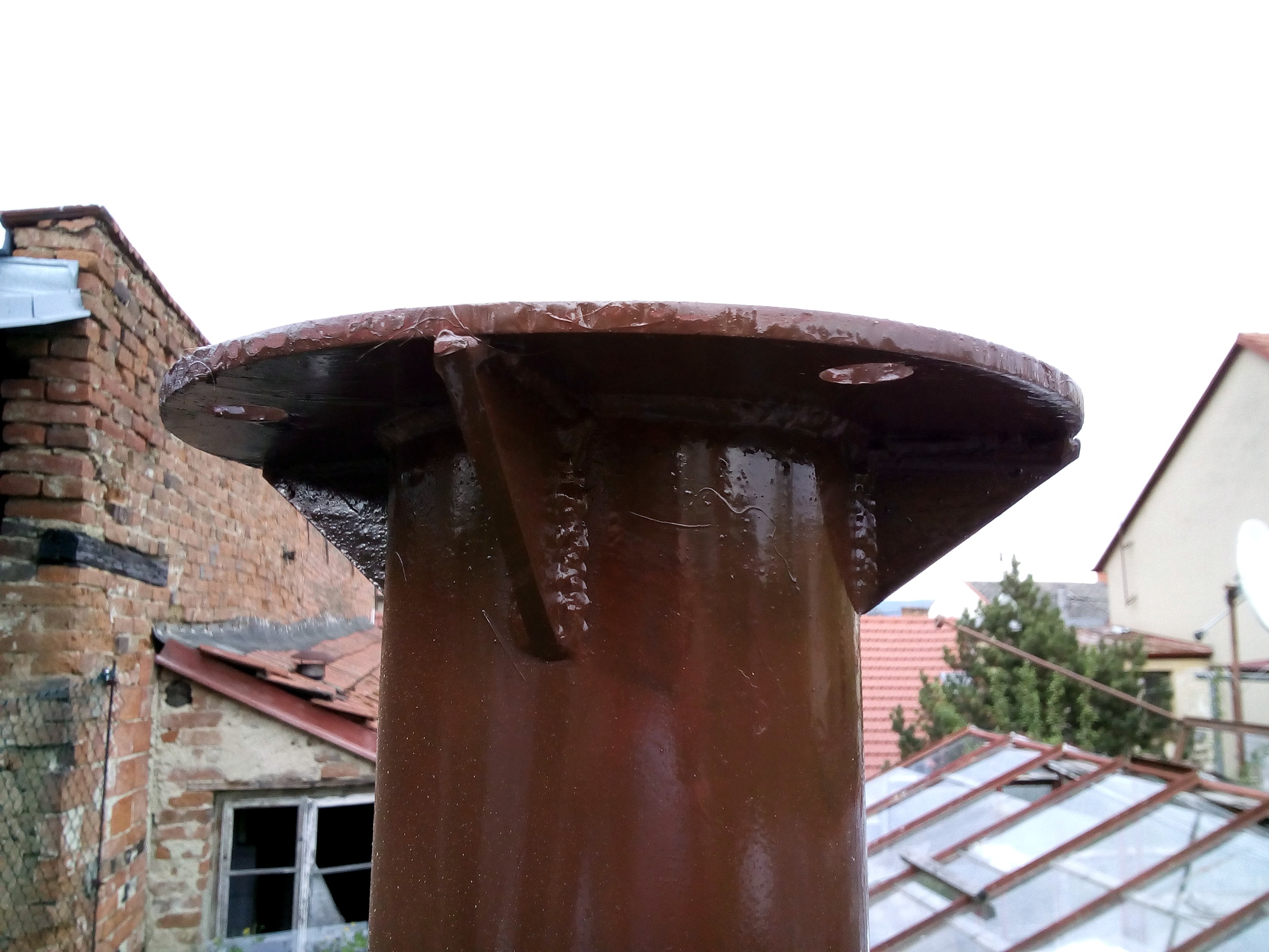
Fig. 11 - Reinforcement detail

Fig. 12 - Mounting holes for EGIS
The last picture is a view of the finished work. This doesn't seem like a complicated thing. But I admit that the whole work gave me enough work. The most difficult final landscaping was for the production of the entire load-bearing structure. I really don't like gardening. Especially the futile weed fight. I guess you can see it. 

Fig. 13 - The whole work of the supporting structure
And a photo of the EGIS positioner attached to the supporting structure. The photo shows the temporary location of my control in a plastic waterproof box at a really minimal distance from the EGIS positioner. I already describe the method of attaching the dish on the website about the Laminas 2700 dish in the menu Parameters.

Fig. 14 - Installed EGIS Robot
21.10.2020 Appendix.
After two months of use, it turned out that I had made one major mistake. The inclined supports keep the support tube in a vertical position, but their flexibility no longer prevents the support tube from rotating about its axis. I thought that the forces acting on the support tube in this way would not be too great. The opposite is true. After attaching the dish, at the slightest breeze, the support tube began to rotate randomly. With a bigger wind, it was already 10 °. So I had to fix the heel of the pipe against rotation. I drilled a Ø 10 mm hole in the pipe. I made a wedge out of the rest of the steel and tightened it with an M10 screw between the two spokes of the base.

Fig. 15 - First fixation against rotation
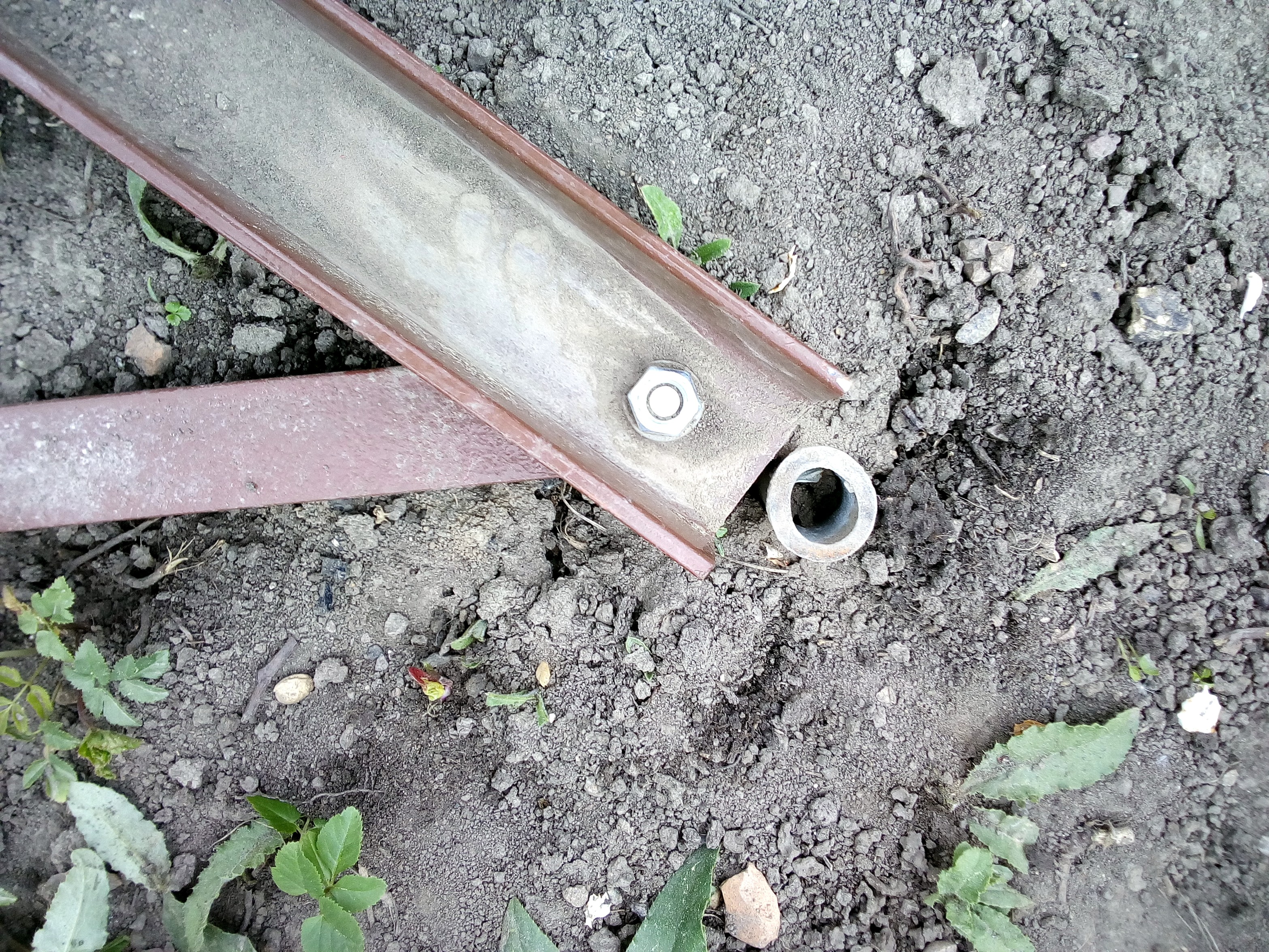
Unfortunately, it turned out that even this solution is not enough. In higher winds, the opposite uncaptured side of the tube moved along the base within ± 1mm, causing a deviation completely outside the receiving satellite. So I had to add a second fixation at an angle of 90 ° to the first handle. To make both fixations reliable, I filled the gaps between the support tube and the notches in the support base with a solid material. Only after this operation did the heel of the support tube stop moving and the setting of the parabola remained stable even in higher winds.
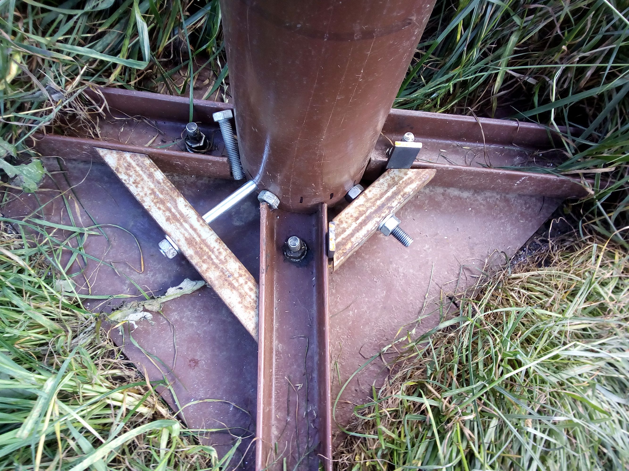
Fig. 16 - Additional fixation against movement
My original attempt to allow the space around the base of the support tube to more precisely adjust its verticality proved to be misleading. It is much more important to secure the heel of the support tube against any movement. This is ensured not only by the wedges firmly tightened by the screws, but also by the mentioned filling of the space around the base of the support tube with material. If I started the construction again, I would pay attention to the high accuracy of the cutouts in the spokes of the base, in order to minimize the possibility of shifting the heel of the inserted pipe. To this measure, the additional double protection against rotation and displacement is an absolute necessity.