HW 2.1 Diagram
At the outset, I must point out that a prototype has not yet been produced and therefore the functionality of the device as a whole has not yet been tested. This is only a theoretical proposal that may contain errors.
The proposed device has the following features:
- rotation speed control of 3 motors 24V=
- reading 4 + 2 sensors with 24V amplitude pulses
- reading 2 sensors with 5V amplitude pulses
- control of 2 servomotors
- making the I2C / 3.3V and SPI / 3.3V buses available on a separate terminal board.
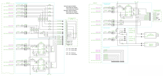
Fig. 1 - HW diagram version 2.1
The scheme is divided into five functional blocks.
1) Block of inputs from the Egis motor unit
This part is basically the same as for HW version 1.0. Input pulses with an amplitude of 24V through a resistance network of 1k5, 560R and 680R power the LEDs in the PC844 optocoupler. This optocoupler creates a galvanic isolation of the Raspberry Pi bus and converts the pulse size to 3.3V. Both impulses from EPR-203 sensors and from Origin switches are processed in the same way. The difference from HW 1.0 is in the GPIOs used to process these signals. All inputs to the Raspberry Pi assume software activation of the internal pullup resistors.
2) Block of outputs to the Egis motor unit
The signal from the GPIO powers the LEDs in the PC844 optocoupler. The optocoupler creates galvanic isolation of the Raspberry Pi bus and converts the size of the signals to TTL 5V level. These signals control the two L6203 DMOS full bridge drivers and through them the direction and speed of rotation of the motors in the EGIS unit. For pins GPIO12 and GPIO 13, HW PWM signal generation is used.
The mentioned two blocks replace the original device HW version 1.0. Other blocks already form extensions that were not in HW version 1.0.
3) Block of inputs/outputs of aditional motor 3
Control of the third engine is the same as the EGIS engines. The HW PWM signal from GPIO 19 and the direction of rotation signal go through the optocoupler PC844 to the DMOS full bridge driver L6203. It controls the direction and speed of rotation of the third motor. The impulses from the sensors of this motor are fed to the GPIO inputs of the Raspberry Pi via the optocoupler.
4) Block of two servo motors
The signal for controlling the servo motors is created using software-generated PWM pulses. This signal is galvanically separated by optocoupler PC844, converted to 5V level and fed to the control input of the servo motor. The polarity of this signal is important, which is ensured by the 3k3 and 100R resistors.
5) Block of special buses
This block is just a wired connection of the Raspberry Pi's I2C and SPI bus to the output terminal block. ATTENTION!!! These buses are not galvanically isolated and careless handling can damage the Raspberry Pi. Note that all these pins operate at a maximum of 3.3V. When working with them, it is necessary to follow the principles of working with components sensitive to electrostatic charge.
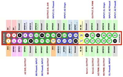
GPIO usage is different from HW version 1.0. Therefore, even the SW intended for HW 1.0 cannot be used for this new design. An overview of the new GPIO usage is in the following figure.
The components used are of standard design with a tolerance of 10% and there is no need to select them in any special way. All resistors are for 0.4W load, metallized, in case 0207/10. All capacitors can be ceramic or foil for voltages greater than 50V. However, the PCB design must take into account the different dimensions of the capacitors. TTL 7404 inverters can be in any variant. I chose the classic Wago W237 screw terminal block.
The 24V source must also have sufficient reserve for a possible third motor. Three L6203 circuits make it possible to switch up to 3 x 5A, that's a total power of up to 360W. But I don't know how big a cooler is needed for continuous operation of such a large power. In addition to the Raspberry Pi, the 5V source must also securely tighten the 2 servo motors. The Raspberry Pi version must have 4 HW PWM channels (3 used so far). An ordinary SD card is sufficient as storage for the software. A USB-connected SSD is not necessary, but it will increase the speed, reliability and lifespan of the computer. The overall overview of the material used is in the following table.
| Part number | Component name | Quantity | Socket |
| 22 | Raspberry Pi 3 B + SD card | 1 | |
| 21 | Source 5V / 3A, or stronger | 1 | |
| 20 | Source MEAN WELL LRS-75-24, or stronger | 1 | |
| 19 | IDE cable flat 40 pin | 1 | |
| 18 | Connector MLW40G | 1 | |
| 17 | Terminal block ARK500/2EX (Wago W237-102) | 4 | |
| 16 | Terminal block ARK500/3EX (Wago W237-103) | 10 | |
| 15 | Condenser 220nF, foil | 3 | |
| 14 | Condenser 22nF, ceramic, foil | 3 | |
| 13 | Condenser 15nF, ceramic, foil | 6 | |
| 12 | Condenser 1nF, ceramic, foil | 4 | |
| 11 | Resistor 3k3 | 8 | 0207/10 |
| 10 | Resistor 1k5 | 14 | 0207/10 |
| 9 | Resistor 750R | 2 | 0207/10 |
| 8 | Resistor 680R | 6 | 0207/10 |
| 7 | Resistor 560R | 6 | 0207/10 |
| 6 | Resistor 410R | 8 | 0207/10 |
| 5 | Resistor 100R | 4 | 0207/10 |
| 4 | Resistor 10R | 3 | 0207/10 |
| 3 | SN74LS04N, 6x inverter with open collector | 1 | PDIP14 |
| 2 | PC844, 4x optocoupler (Vishay ILQ620) | 4 | PDIP16 |
| 1 | L6203, DMOS full bridge driver | 3 | Multiwatt11 |


