
")
")
")
HW 2.0 solution design
After about two months of experience with the operation of my control unit for the EGIS positioner, I have extended the original requirements with additional features. This started a new version of HW 2.0. This version will not be compatible with HW ver.1.0. This is because the new features require a connection to the Raspberry Pi on the GPIO port pins, which have already been used for something else. That is why I have stopped the development of HW version 1.0 and what will continue to be created will gradually replace everything I have published here so far. But since I'm sorry to just throw away the work I've already done, I'll gradually move it to the archive. There it will be available to anyone who would like to return to it and view it.
So I set these extended requirements for the new control unit:
- Control both azimuth and elevation motors simultaneously
- For both motors, enable PWM speed control for smooth start and stop
- Complete the design with servomotor control for setting the skew LNB
- Ensure the correct function of the control unit even when connected to the EGIS positioner with 10 m long cables
- Control the entire unit via Ethernet, either by cable or via Wi-Fi
- Do not interfere with the electronics of the motors.
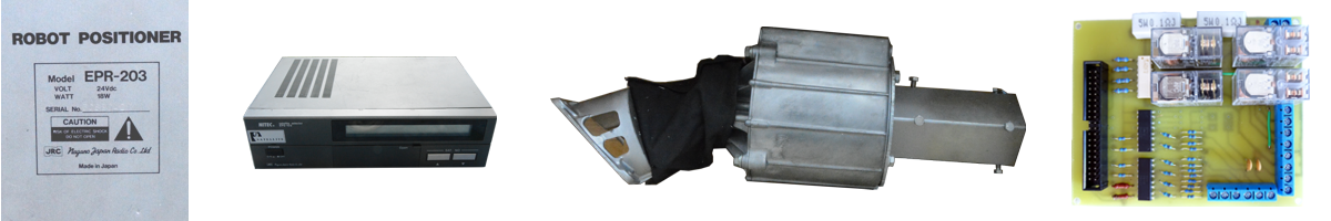
The main reason for the design change was the high speed of both EGIS engines. After connecting 24V via a relay, the motors started too fast. This created a great dynamic impact on the entire dish and its components. This shock was transmitted back to the mechanical components of the EGIS positioner due to the rocking of the dish. Therefore, I had a legitimate concern that these repeated shocks would reduce the life of both the EGIS positioner and the entire large dish.
Unpleasant experience with the destruction of the first version of the control unit has shown that protecting electronics from air humidity is not a simple matter. Therefore, I decided to try connecting the new control unit to the EGIS positioner using 10 m long cables. This could allow for possible placement in a sheltered site from direct weather conditions.
Another absolutely necessary addition to the twin-motor rotation of the dish is the possibility to set the skew for LNBs with linear polarization. Of course, this is no longer related to the construction of the EGIS positioner, a separate LNB recording unit must be created. But its control is logically related to the routing of the dish and therefore this additional unit should be controlled by the same program. It turned out that you can buy a relatively small but powerful model servomotor, which is excellent for the design of LNB shooting. That's why I added its support to HW ver.2.0.
The control unit remains my favorite computer Raspberry Pi 3. Older versions cannot be used due to the small number of HW channels PWM and servo control. HW control could be replaced by software control, but since the Linux Raspbian operating system is not real-time, it would be difficult to check in amateur conditions whether the performance of older Raspberry Pi types is sufficient for smooth SW control of controlled motors.
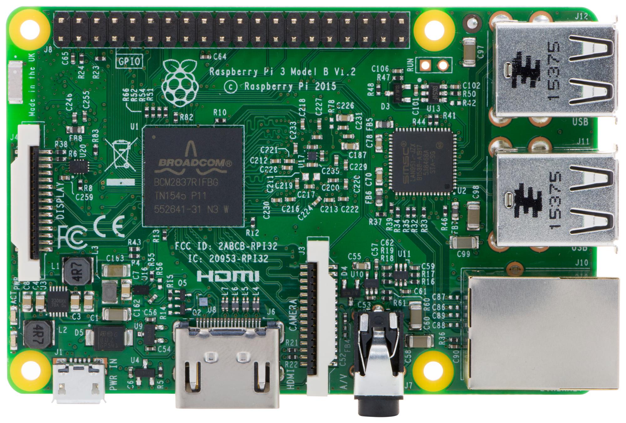
Fig. 1 - Computer Raspberry Pi
Another construction block remains the 24V / 75W power supply type MEAN WELL LRS-75-24. Its dimensions are 99x97x30mm. It is able to supply almost twice the power needed to run both engines simultaneously. It has internal protections for overload, mains overvoltage and overheating. Since there is also a version 36V / 100W MEAN WELL LRS-100-36, I am considering the possibility of simultaneous development of another version of HW 2.0A for controlling conventional traction motors. The difference between the two versions would be, in addition to the type of source, only in the input resistance network setting the optimal current through the LEDs of the isolating optocouplers. When I test the prototypes, it may turn out that it will be possible to choose one common compromise solution for 24V and 36 V power supply. But for now, I assume that the voltage difference is too large and the resistance networks will have to be different.
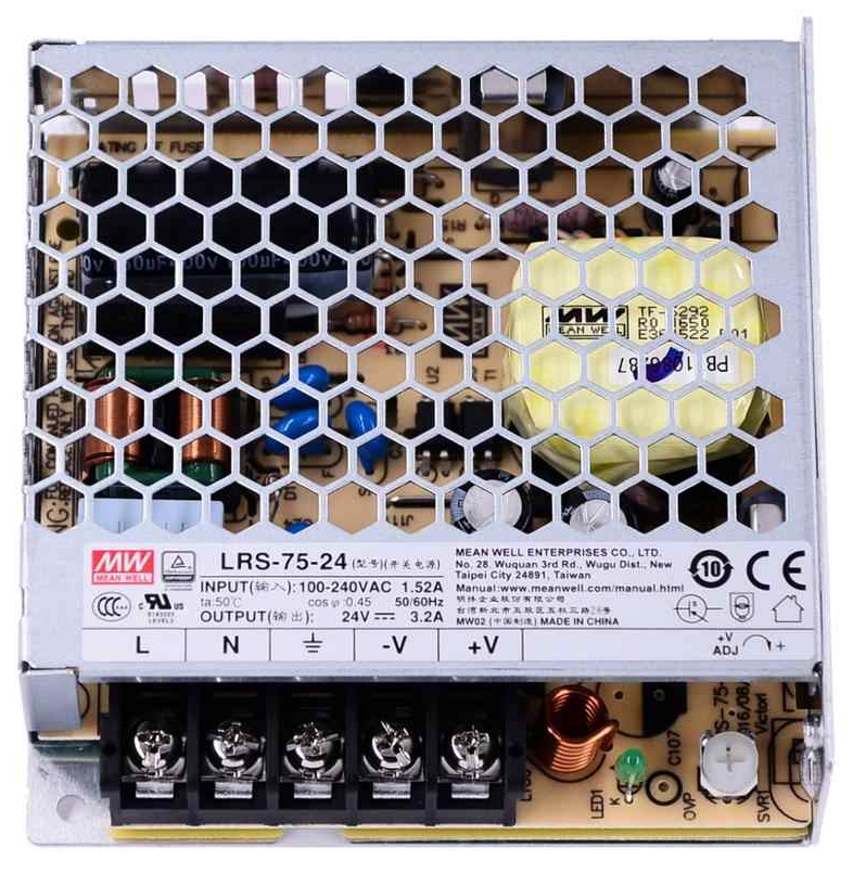
Fig. 2 - Switching power supply module MEAN WELL LRS-75-24
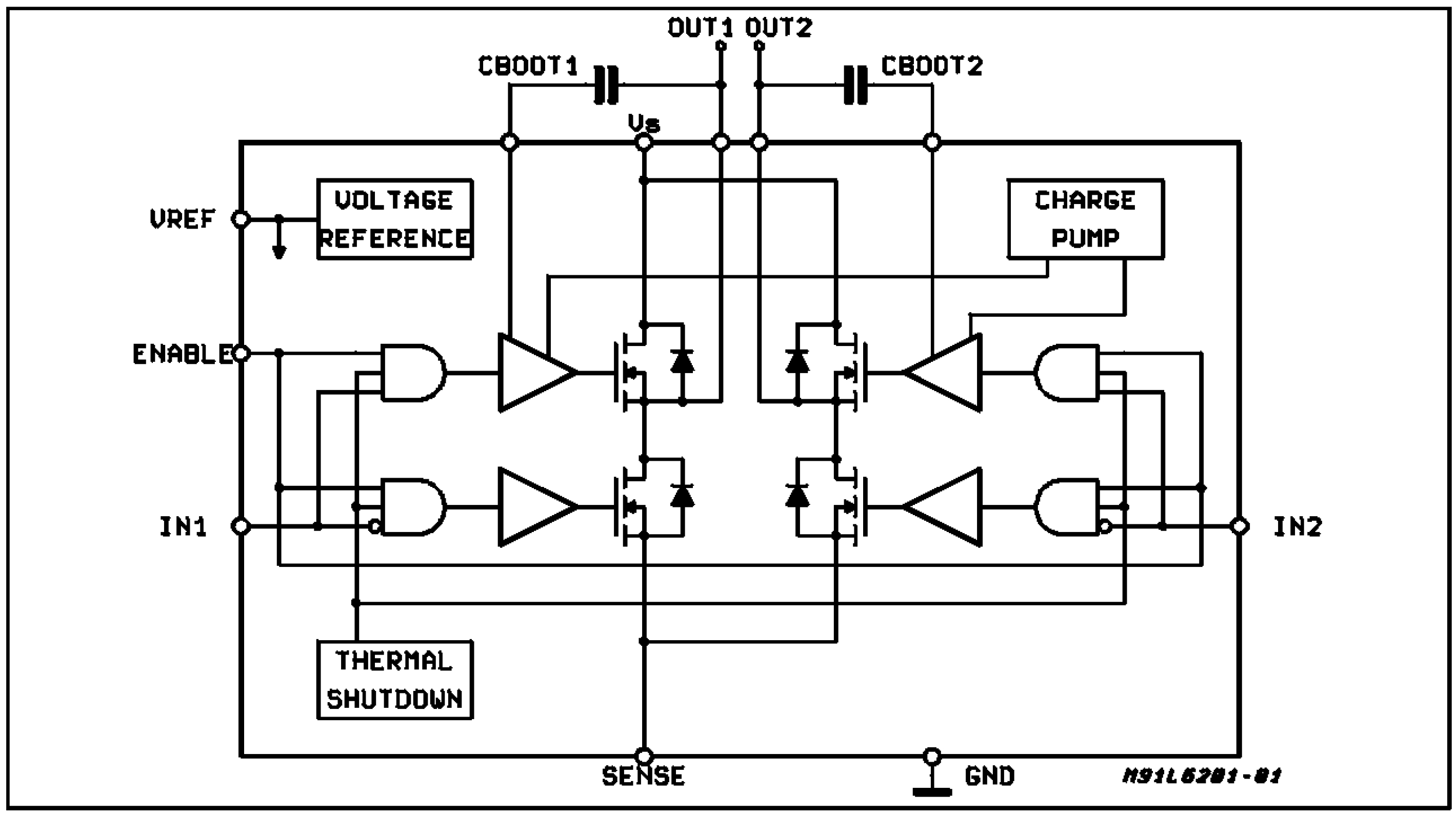
From the principle of PWM speed control of DC motors, it is clear that the relays used in HW ver.1.0 must be replaced by semiconductor switching elements. Here it is difficult to decide what power they should be able to switch. Whether to focus only on the consumption of the EGIS positioner motors, or to choose an even larger power reserve for possible experiments with motors and structures of other types. Due to the need to cool semiconductor switching elements, especially in the summer, I decided not to try anything extreme. I am not an engineer who can calculate the necessary dimensions of cooling blocks on paper. My choice will be more experimental. That's why I stayed on the ground. Finally, I chose the L6203 circuit containing a complete power switching bridge with DMOS transistors. It can switch voltages up to 48 V and currents up to 5A. That should be enough with caution to prevent it from overheating.
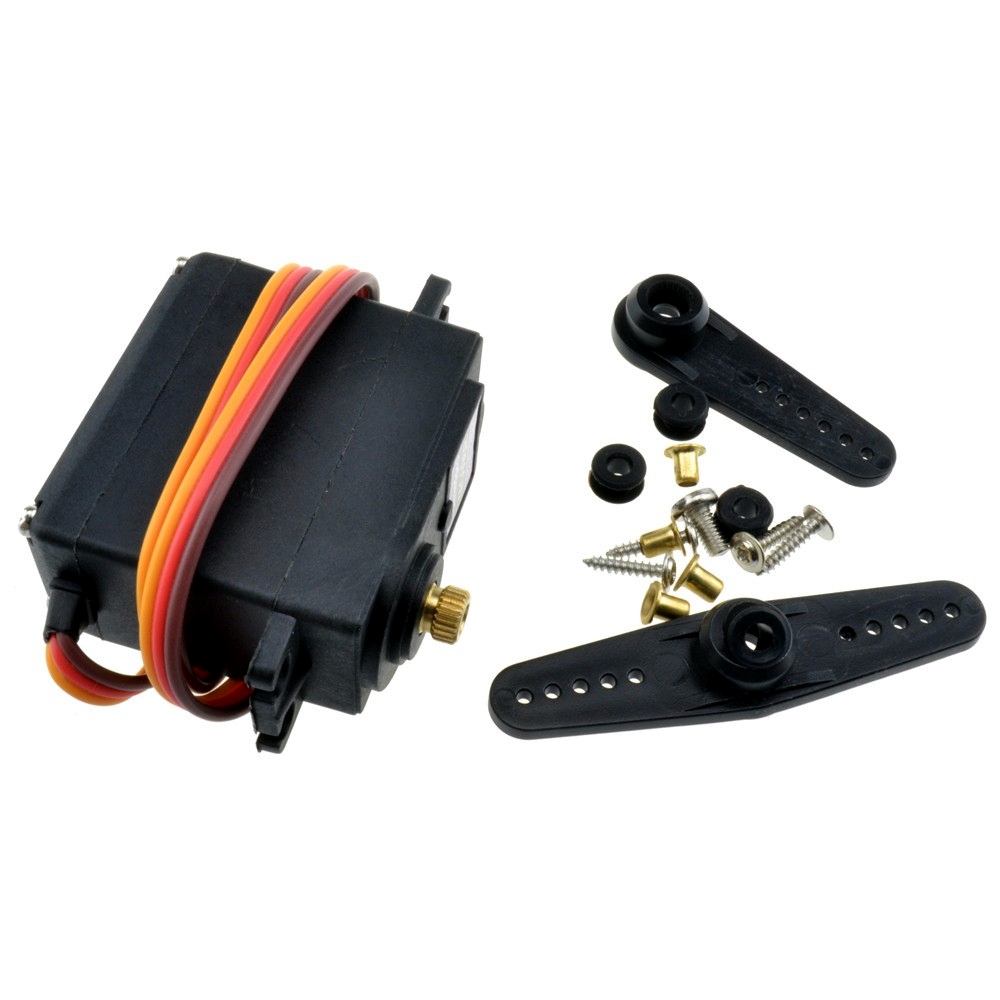
I chose the MG996R as the servomotor for the LNB rotation drive. On the one hand, it contains metal gears and on the other hand it has a torque of 15 kg / cm at 6V. This should ensure sufficient performance and reliability, although I have no idea yet about the specific solution of the skew setting unit.
So that's roughly my current idea of a new control unit design. If you have any small advice, questions or comments about it, write them in the comments at the end of the article. If you would like to embark on a wider discussion, try the discussion forum here.